
Power and current
20 kW to Amps at 415 V: Three-Phase Worked Example
At 415 V three phase, 20 kW electrical input gives 34.78 A at power factor 0.80; shaft output requires an efficiency adjustment.
Read article →
ELECTRICALDYEV ARTICLES
Practical engineering explainers, worked examples and field notes. Every article links to a relevant tool and makes its assumptions and limits clear.
Choose a path when several formulas depend on the same voltage, current or equipment assumptions.
A three-phase answer depends on where voltage and current are measured. This route starts at the conductors and ends with the limits of the balanced model.
A transformer nameplate, a calculated full-load current and a measured loading percentage describe different things. Follow them in that order.
A voltage-drop result is only as useful as its conductor data and route assumptions. Choose a method that matches the information you actually have.
Power and current
At 415 V three phase, 20 kW electrical input gives 34.78 A at power factor 0.80; shaft output requires an efficiency adjustment.
Read article →
Power and current
Ten amperes gives 1.84 kW at 230 V single phase or 5.75 kW at 415 V three phase when PF is 0.80.
Read article →
Power and current
Amps are a snapshot of current; kWh needs active power and time. Work through one single-phase and one three-phase operating interval.
Read article →
Power and current
A transparent explanation of the familiar √3 relationship, the voltage that belongs in it and the conditions under which it is useful.
Read article →
Power and current
The kVAr formula is straightforward. Choosing equipment safely still requires harmonic, resonance and switching studies.
Read article →
Power and current
A practical guide to the relationship between power, voltage, power factor, efficiency and line current.
Read article →
Power and current
Current alone is not power. Voltage, phase arrangement and power factor determine what a measured ampere value can tell you about kW.
Read article →
Power and current
These three quantities are related, but they answer different questions about an AC load and its effect on the supply.
Read article →
Power and current
100 A, 80 A and 60 A produce a 34.64 A fundamental neutral-current estimate at 120° separation; harmonics need a separate check.
Read article →
Power and current
A transformer keeps approximately the same apparent-power rating across both sides, but current changes as voltage changes.
Read article →
Power and current
The √3 factor is geometry, not a memorised correction. It connects phase quantities with line quantities in a balanced system.
Read article →
Power and current
Power factor changes current without changing the active kW requirement. A short table makes the effect easy to see.
Read article →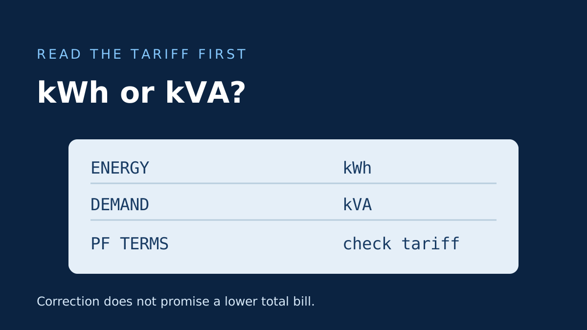
Power and current
A lower kVA demand can affect some tariffs, but it does not automatically reduce a meter's kWh total or every electricity bill.
Read article →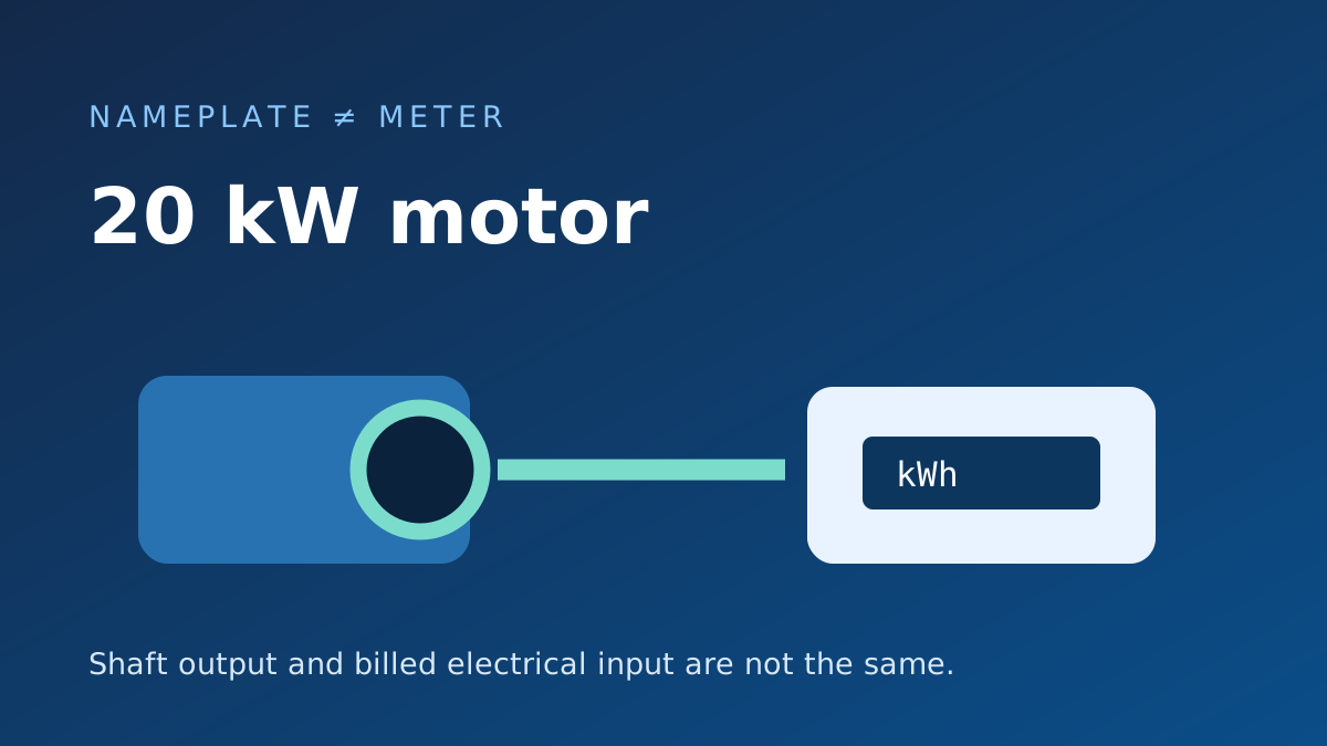
Power and current
Twenty kilowatts on a motor is not automatically twenty kilowatt-hours on the meter every hour; rating basis and actual loading matter.
Read article →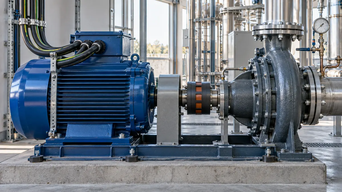
Power and current
A motor’s shaft output is smaller than its electrical input. Correct conversion begins by identifying which side of the machine the rating describes.
Read article →Power and current
The same kVA rating produces different current at different voltages. Start with the phase arrangement and the voltage reference.
Read article →
Power and current
Star: line current equals winding current. Delta: line current is √3 times branch current, assuming balanced sinusoidal operation.
Read article →
Power and current
In an ideal balanced star system, line-to-line voltage is √3 times line-to-neutral voltage. The measurement points still matter.
Read article →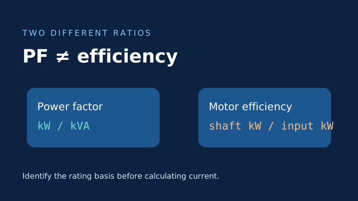
Power and current
Both affect a motor-current estimate, but at different steps. Mixing them can hide the power basis or apply a factor twice.
Read article →Power and current
Single-phase current depends on what the power rating means. Electrical kW, apparent kVA and mechanical output need different inputs.
Read article →
Measurements and equipment
The clamp reading is valuable, but it is one input. Voltage, phase arrangement, power factor and timing complete the power estimate.
Read article →
Measurements and equipment
A nameplate already contains many of the assumptions a calculator would otherwise have to guess. Read them as one matched rating set.
Read article →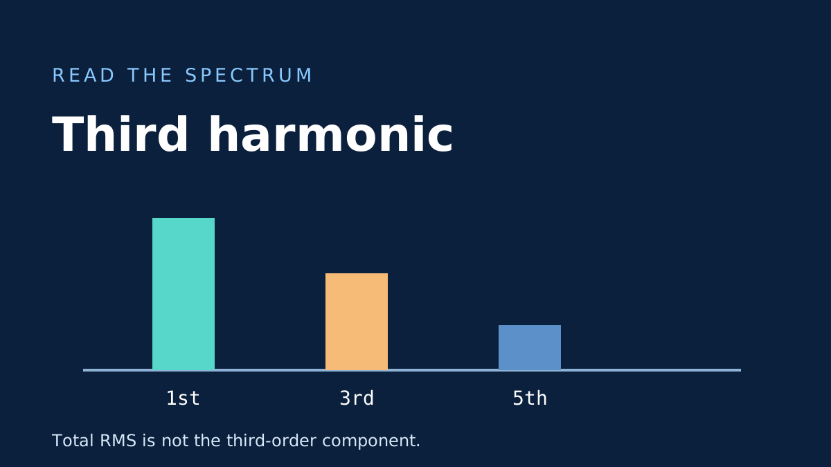
Measurements and equipment
A display that says 100 A is not telling you the third-harmonic current. Find the spectrum's actual third-order RMS row first.
Read article →
Measurements and equipment
A balanced fundamental can cancel in the neutral while harmonic current remains. Interpret the reading before comparing it with a simple calculation.
Read article →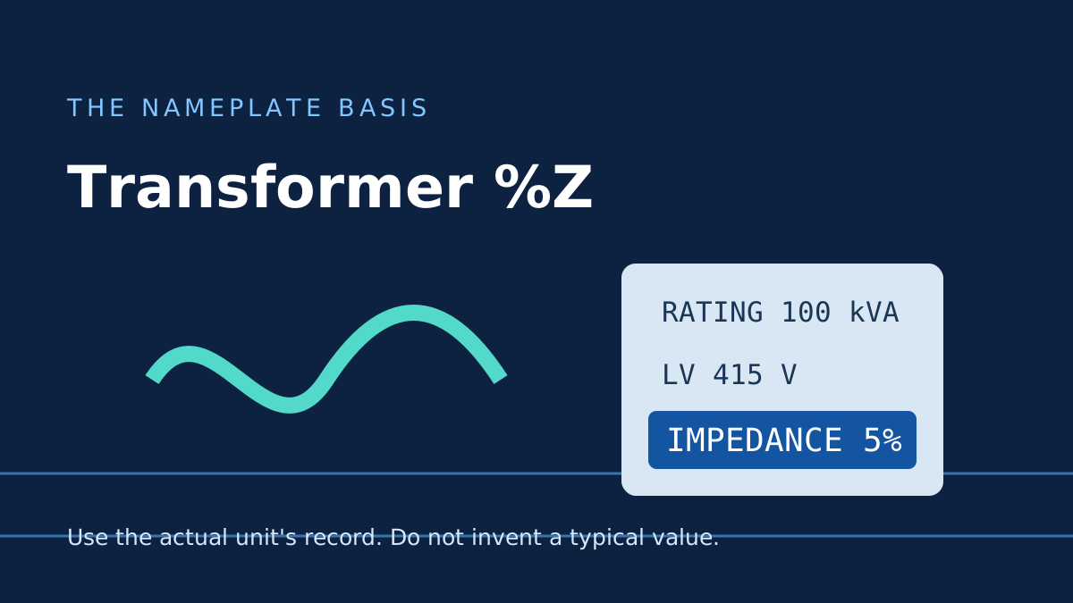
Measurements and equipment
The %Z printed on a transformer is not a voltage-drop target. It describes an impedance measurement at a defined test condition.
Read article →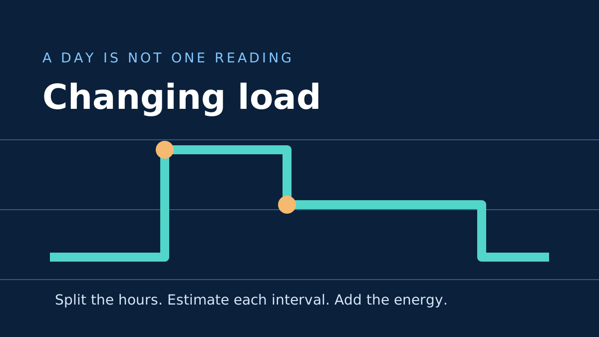
Measurements and equipment
A pump that starts, idles and runs at full load does not draw one current all day. A short interval worksheet gives a more honest energy estimate.
Read article →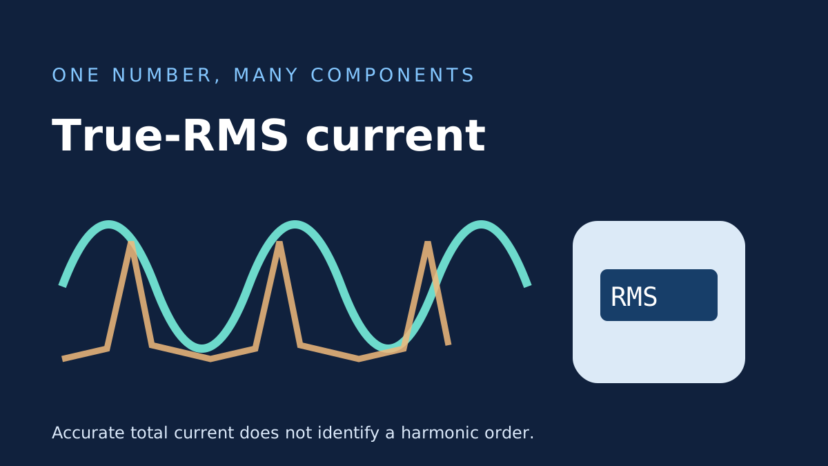
Measurements and equipment
True-RMS is valuable for a distorted current waveform, but it does not identify which frequency components produced the number.
Read article →Measurements and equipment
Three phase-current magnitudes are not the whole waveform. A neutral reading can expose assumptions that a simple calculation cannot represent.
Read article →Measurements and equipment
At 415 V and 100 A on a balanced three-phase 100 kVA transformer, apparent-power loading is about 71.88% of nameplate.
Read article →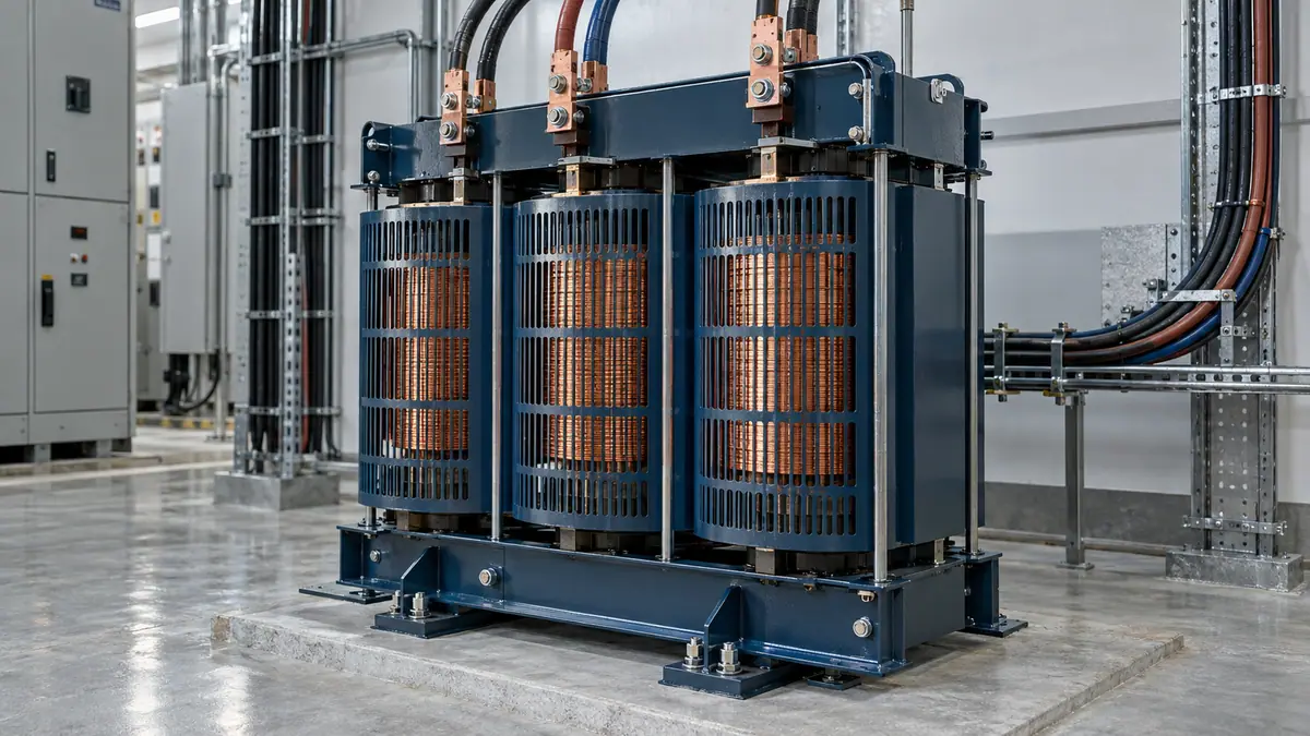
Measurements and equipment
The same 100 kVA can accompany 80 kW at PF 0.80 or 95 kW at PF 0.95. The nameplate is not a fixed kW output.
Read article →
Protection and project workflow
A 32 A breaker label tells you about nominal current. It does not say the device can interrupt every possible fault at that point.
Read article →
Protection and project workflow
A load schedule should explain where its totals came from, not just produce one large kW number at the bottom.
Read article →
Protection and project workflow
Correction factors multiply. Their source conditions and applicability matter as much as the arithmetic.
Read article →
Protection and project workflow
23 A ≤ 25 A ≤ 28 A passes this preliminary current comparison; a 32 A breaker with the same cable capacity does not.
Read article →
Protection and project workflow
The three symbols describe load, protective device and conductor. Keeping them separate prevents circular sizing logic.
Read article →
Protection and project workflow
Ib, In and Iz are a useful first check, but they do not determine breaking capacity, selectivity or fault protection.
Read article →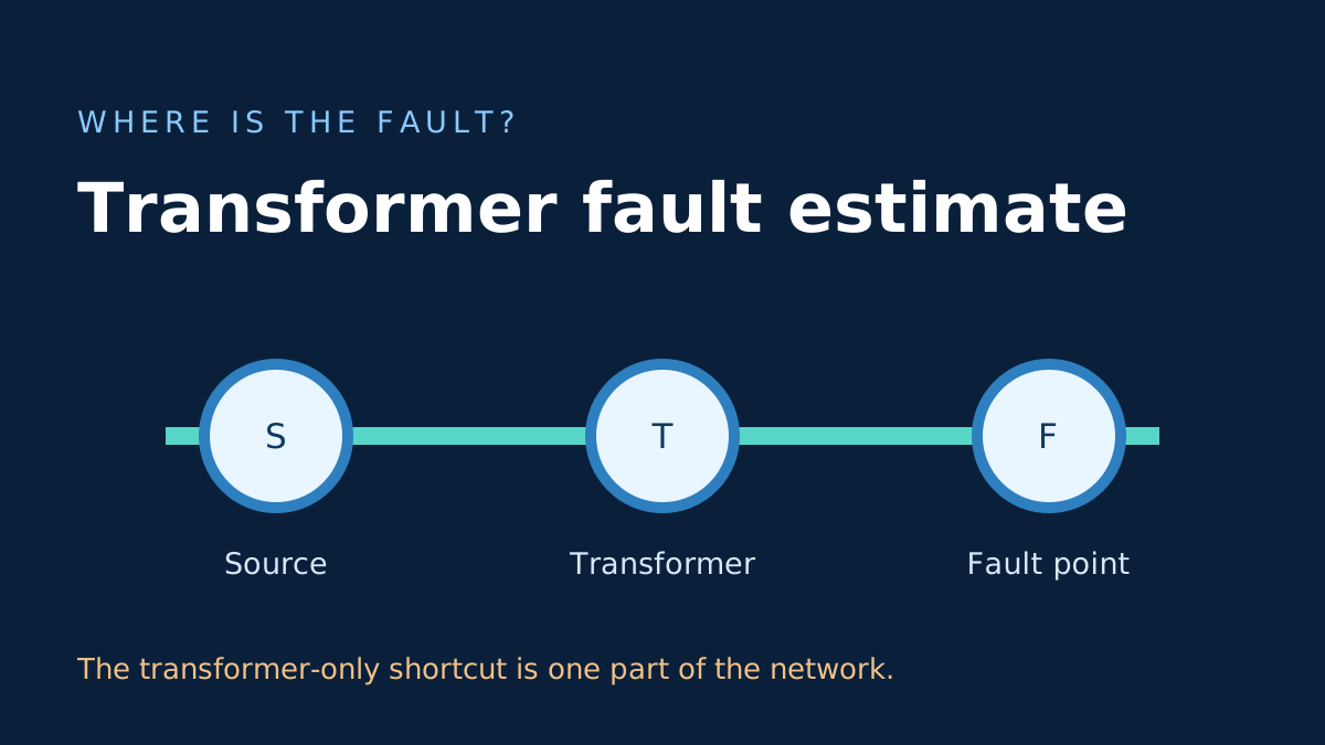
Protection and project workflow
Dividing full-load current by %Z is useful for understanding a transformer, but the available fault current at a board needs more information.
Read article →
Protection and project workflow
A percentage impedance can turn rated current into a rough terminal-fault estimate, but source and circuit impedances change the real result.
Read article →
Voltage drop and conductors
Maximum route length is an inverse voltage-drop calculation, not a complete cable-sizing decision.
Read article →
Voltage drop and conductors
mV/A/m means millivolts per ampere per metre. The value must match the cable and circuit arrangement in its source data.
Read article →
Voltage drop and conductors
A substituted example shows where √3, route length, resistance, reactance and power factor enter the result.
Read article →
Voltage drop and conductors
Voltage drop is easy to calculate badly. The important work is choosing matching conductor data, geometry and route length.
Read article →
Voltage drop and conductors
In an illustrative copper model, resistance rises about 23.6% from 20°C to 80°C; ambient air alone does not tell you conductor temperature.
Read article →
Voltage drop and conductors
Material changes resistance, but a practical cable choice also involves size, joints, installation, thermal behavior and product data.
Read article →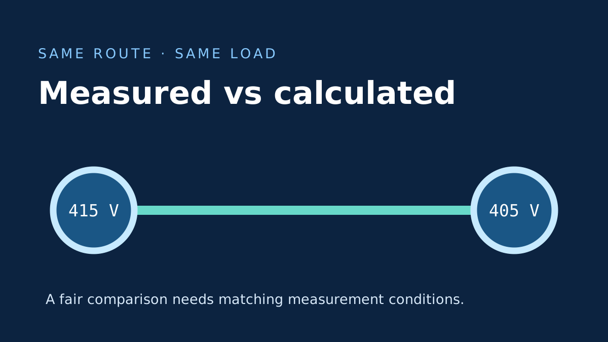
Voltage drop and conductors
A calculated drop and a field reading are only comparable when the measurement points, load current and operating condition match.
Read article →
Voltage drop and conductors
Length errors often come from counting the return path twice. Start by identifying the geometry built into the selected formula or coefficient.
Read article →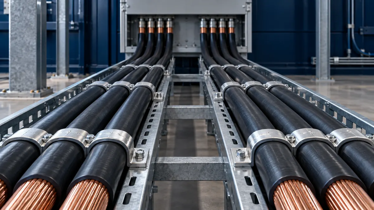
Voltage drop and conductors
Two identical paths can halve effective impedance in a simple model. Unequal paths do not automatically share current equally.
Read article →
Voltage drop and conductors
Cable sizing is a comparison of constraints, not a lookup of load current against one universal table.
Read article →
Voltage drop and conductors
R and X do not contribute identically to the in-phase voltage change. Power factor sets the weighting in the common approximation.
Read article →