
Voltage drop and conductors
Parallel cable runs: what changes in a voltage-drop calculation
Two identical paths can halve effective impedance in a simple model. Unequal paths do not automatically share current equally.
Check parallel-run voltage drop →Published 26 September 2026
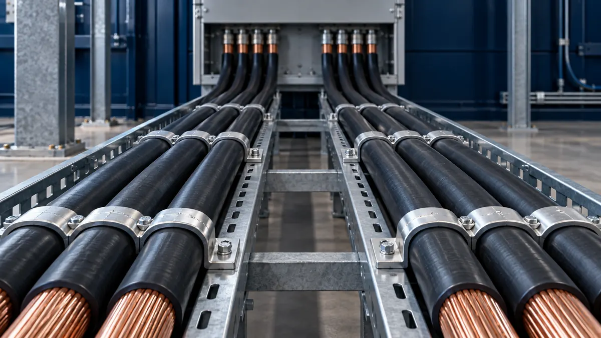
The ideal equal-path model
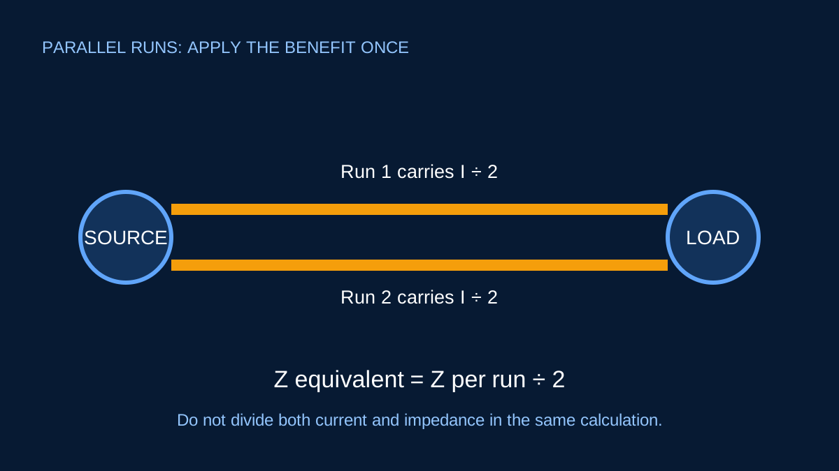
For n identical impedances in parallel, effective impedance is the impedance of one path divided by n. If total current divides equally, each run carries I / n, and the voltage across every path is the same.
In a voltage-drop formula this can be represented by dividing the impedance contribution by the number of parallel runs once. Two equal paths produce half the drop of one path at the same total current.
A quick example
Suppose one cable run produces 6 V drop at 60 A under the stated conditions. With two genuinely equal parallel runs, the simplified result is 3 V. Each run carries approximately 30 A.
Dividing both current and impedance by two inside the same total-current formula would count the benefit twice. ElectricalDyev keeps total load current and applies the run count once.
Why real paths can share unequally
Current sharing depends on impedance, and impedance depends on more than conductor area. Length, material, temperature, conductor arrangement, joint resistance and magnetic effects can all matter. A shorter route or better termination can take more current and become hotter, which then changes its resistance.
Parallel single-core AC conductors also need appropriate physical arrangement so inductive effects remain comparable. The exact design is not captured by a single run-count field.
Ampacity factors do not disappear
Putting conductors in parallel does not mean each retains an isolated free-air rating. Grouping, ambient temperature, containment and installation method still affect current-carrying capacity. Apply the relevant reviewed data to the actual arrangement.
Protection must also account for how faults and overloads affect the parallel paths and their common terminations.
What to verify
- Same material, cross-sectional area and construction.
- Closely matched route length and arrangement.
- Suitable common terminations and connection quality.
- Expected current sharing under operating temperature.
- Installation and protection requirements for parallel conductors.
Use the calculator as a comparison
The parallel-run input is useful for early route comparisons and for checking whether the arithmetic applies the division only once. It is not proof that the proposed conductors will share equally or that paralleling is permitted for a particular installation.
Document the equal-sharing assumption beside the result and replace it with project-specific conductor data and review before construction.
Two equivalent ways to calculate—choose one
Suppose a circuit carries 200 A through two identical parallel runs. One method assigns 100 A to each run and uses the full per-run impedance. The other keeps 200 A as the total and divides the impedance by two. Both produce the same ideal voltage drop.
The error occurs when a worksheet uses 100 A and also divides impedance by two. That predicts one quarter of the single-run drop instead of one half. ElectricalDyev treats entered current as total circuit current and divides the impedance or mV/A/m value by the number of equal runs once.
Why conductors may not share equally
Small resistance or reactance differences can change current distribution. Unequal lengths, different routes, inconsistent lug preparation, different conductor temperatures and asymmetric phase spacing all matter. Current sharing can also evolve as one conductor warms and its resistance changes.
The proposed runs should use matching conductor material, size, construction and length, with consistent terminations and routing. Applicable rules may impose additional restrictions on parallel conductors. A calculation option cannot verify any of those physical conditions.
Ampacity is not simply multiplied without context
Two cables do not always provide exactly twice the usable ampacity. Grouping and installation conditions can reduce heat dissipation, and correction factors may apply to the group. Termination ratings and current balance can also govern.
Keep the voltage-drop parallel-run calculation separate from corrected ampacity. The first describes ideal electrical impedance sharing; the second addresses thermal current-carrying capacity under installation conditions.
Check fault and protection behaviour
Parallel paths also share fault current. Each conductor and termination needs adequate thermal and mechanical performance, and protective arrangements must account for the complete circuit. A failed or disconnected path can leave remaining conductors carrying more load than intended.
For commissioning or investigation, measure each parallel conductor under representative load with appropriate equipment. Store the individual readings rather than only their sum. A significant imbalance is a reason to investigate—not a number to average away.
Sources and limits
Preliminary engineering aid only. Parallel conductor suitability, current sharing and installation rules require project-specific professional review beyond the simplified arithmetic.
Verify applicable laws, standards, manufacturer data and project conditions with a qualified electrical professional before construction, procurement or regulatory submission.
CONTINUE READING
Related articles
Voltage drop and conductors
Voltage drop: route length, conductor data and useful checks
Voltage drop is easy to calculate badly. The important work is choosing matching conductor data, geometry and route length.
Voltage drop and conductors
One-way route length versus total conductor length
Length errors often come from counting the return path twice. Start by identifying the geometry built into the selected formula or coefficient.
Protection and project workflow
How cable correction factors combine
Correction factors multiply. Their source conditions and applicability matter as much as the arithmetic.