
Protection and project workflow
Building a load schedule that shows demand and phase balance
A load schedule should explain where its totals came from, not just produce one large kW number at the bottom.
Open the local load-schedule workspace →Published 26 September 2026

Begin with rows another person can understand
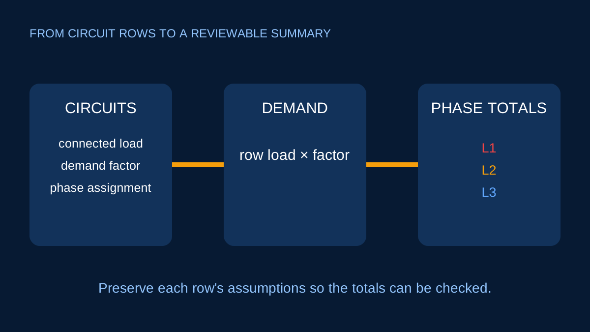
A useful row identifies the circuit or load, quantity, unit rating, supply arrangement, voltage, power factor and phase assignment. If demand is applied, record the factor rather than replacing the connected value with a smaller unexplained number.
Connected load and demand load answer different questions. Keeping both lets a reviewer see the assumption.
Connected and demand totals
If four identical loads are 2 kW each, connected load is 8 kW. With a justified row demand factor of 0.75:
Demand load = 4 × 2 × 0.75 = 6 kW
That does not mean each unit has been resized to 1.5 kW. It means the schedule assumes the group’s coincident demand for the stated purpose is 6 kW.
Demand factors should not be copied between unrelated projects. Operating patterns, standby duty, controls and the governing design method matter.
Convert each row using its own system
A 230 V single-phase row uses I = P / (V × PF) and contributes to its assigned line. A balanced 415 V three-phase row uses I = P / (√3 × VLL × PF) and contributes that line current equally to L1, L2 and L3.
Do not divide a balanced three-phase line current by three before adding it to the phase totals. Each line carries the calculated line current.
DC rows can contribute to connected and demand power while remaining outside an AC L1/L2/L3 balance summary.
Read phase balance as a planning signal
Phase totals help distribute single-phase circuits. They are not a prediction that every load will operate simultaneously at the scheduled values. A design can look balanced on paper while operating measurements vary by time.
Neutral current also cannot be inferred from simple phase-current totals when nonlinear loads and harmonics are important. The fundamental vector calculator is a separate limited check.
Keep validation visible
Contradictory rows—such as a three-phase system assigned only to L1—should not disappear into totals. The workspace reports the problem and excludes invalid rows until corrected. This avoids a plausible-looking summary built from inconsistent inputs.
Preserve the assumptions
ElectricalDyev stores projects in the browser. A printable report and exported JSON can preserve row inputs, warnings, formulas and timestamps for review. They do not turn the schedule into an approved design.
Use the schedule to organise the load model. Then complete conductor, voltage-drop, protection, fault and applicable regulatory checks circuit by circuit.
Give every row one clear electrical basis
A useful row identifies the load, quantity, unit load, phase arrangement, voltage, power factor and demand factor. It should also distinguish electrical input from mechanical output. If a row says only “pump 7.5 kW”, a reviewer cannot know whether efficiency still needs to be applied.
Keep source notes for fixed equipment and state assumptions for provisional loads. When a value changes, update the row rather than manually adjusting a total. This keeps the schedule auditable.
Connected load and demand load answer different questions
Connected load is the sum of installed ratings on the chosen basis. Demand load applies row-level factors representing the selected operating scenario. A 10 kW row with a 0.60 demand factor contributes 6 kW to that scenario, but the connected equipment remains 10 kW.
Demand factors are not universal constants. They depend on operation, diversity, duty and project requirements. Store the factor and its reasoning at row level so the total can be reconstructed. Do not apply a second unexplained factor to the already-demanded grand total.
Balanced three-phase circuits belong on all phases
A balanced three-phase circuit has the same line-current magnitude in L1, L2 and L3. It should therefore add that current to each phase total. Dividing its line current by three understates conductor current; assigning it to only one phase creates a false imbalance.
Single-phase circuits add only to their assigned phase. A 3P circuit and an L1 circuit can coexist: the three-phase contribution appears in all three totals, while the single-phase contribution raises L1 alone.
Make imbalance a visible scenario
One descriptive percentage is useful for comparing schedules, but it is not a universal acceptance limit. The operating imbalance changes when loads cycle. Review the actual phase totals, the largest and smallest values, and which rows drive the spread.
Try reassignment scenarios for movable single-phase circuits, then document the chosen arrangement. For existing installations, compare the schedule with simultaneous measurements rather than expecting nameplate arithmetic to reproduce every operating moment.
Carry the schedule into downstream checks
Use each row’s design current in the voltage-drop, cable and preliminary breaker workflows. Preserve formula IDs, custom-data provenance and warnings when results are saved back to the project. A schedule total cannot replace circuit-level checks because routes, conductor data and protective conditions differ.
Export the browser-local project before major edits and include a printed review snapshot when sharing. The local-first model keeps client and project details off the server by default, but the exported file should still be handled as project information.
Sources and limits
Preliminary engineering aid only. Demand and diversity assumptions are project-specific and must be justified under the applicable design requirements.
Verify applicable laws, standards, manufacturer data and project conditions with a qualified electrical professional before construction, procurement or regulatory submission.
CONTINUE READING
Related articles
Power and current
Balanced three-phase current: the preliminary calculation
A transparent explanation of the familiar √3 relationship, the voltage that belongs in it and the conditions under which it is useful.
Power and current
Where neutral current comes from in a three-phase system
Equal phase currents cancel in the neutral only under specific waveform and phase conditions. Here is what the familiar vector calculation includes.
Protection and project workflow
Ib, In and Iz: the three currents in a basic breaker check
The three symbols describe load, protective device and conductor. Keeping them separate prevents circular sizing logic.