
Protection and project workflow
Transformer Fault Current: What the Infinite-Source Shortcut Leaves Out
Dividing full-load current by %Z is useful for understanding a transformer, but the available fault current at a board needs more information.
Review the narrow shortcut →Published 25 October 2026
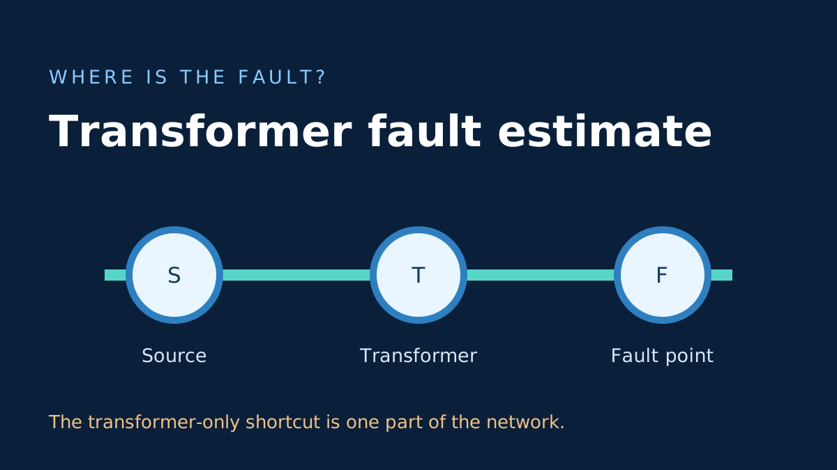
A useful shortcut with a very small boundary
The familiar equation I_fault = I_FL / (%Z / 100) takes a transformer nameplate rating and impedance and produces a simplified symmetrical three-phase RMS value at the transformer secondary terminals. It assumes the upstream source can supply current without its own limiting impedance. It says nothing about a fault farther down a feeder.
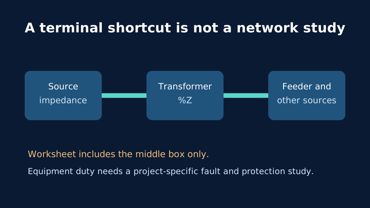
The transformer terminal worksheet deliberately stops there. For a 100 kVA, 415 V, 5% transformer it calculates about 139.12 A full-load current and 2.78 kA from that narrow shortcut. Those numbers are traceable, but being traceable does not make them complete.
What changes as the fault moves
The supply network behind the transformer has impedance. The transformer itself has both resistive and reactive components. A feeder adds conductor impedance between the transformer and a downstream board. These effects can reduce the contribution arriving from the source at the downstream fault location. Eaton’s point-to-point guide treats those pieces explicitly rather than assuming every fault occurs at the transformer terminals.
Other sources can also contribute. Motors, generators and connected power electronics may affect the current seen by equipment during a fault. Transformer impedance tolerance and operating voltage variation change the inputs to a maximum-duty assessment. The shortcut is therefore not an unconditional maximum, nor a way to decide a breaker rating from one number.
Three questions to keep separate
- What does the transformer-only calculation show under its stated assumption?
- What prospective fault current exists at the actual equipment location for the relevant fault types and operating conditions?
- What do the protective devices and equipment have to interrupt, withstand and coordinate with?
Only the first question is answered by the simple worksheet. The percentage-impedance explainer covers where the entered value comes from; breaker rating versus breaking capacity explains why a nominal current label is a different issue.
A responsible handoff
Record the transformer ID and nameplate, nominal and actual voltage basis, upstream source information, conductors, connected rotating or converter loads, and location of the proposed fault. Ask the project electrical professional to perform the appropriate network and protection study. Do not apply a fixed safety multiplier to this article’s shortcut and call that a completed design.
Sources and limits
Preliminary engineering aid only. This article illustrates omitted variables and must not be used to select fault-rated equipment, protection settings or arc-flash controls.
Verify applicable laws, standards, manufacturer data and project conditions with a qualified electrical professional before construction, procurement or regulatory submission.
CONTINUE READING
Related articles
Measurements and equipment
What Transformer Percentage Impedance on the Nameplate Means
The %Z printed on a transformer is not a voltage-drop target. It describes an impedance measurement at a defined test condition.
Protection and project workflow
Transformer Percentage Impedance and Fault Current: A Worked Estimate
A percentage impedance can turn rated current into a rough terminal-fault estimate, but source and circuit impedances change the real result.
Protection and project workflow
Breaker current rating is not breaking capacity
A 32 A breaker label tells you about nominal current. It does not say the device can interrupt every possible fault at that point.