
Protection and project workflow
Ib, In and Iz: the three currents in a basic breaker check
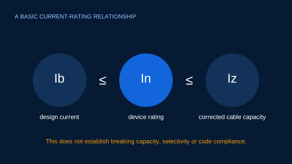
The three symbols describe load, protective device and conductor. Keeping them separate prevents circular sizing logic.
Open the Ib ≤ In ≤ Iz helper →Published 26 September 2026

Ib belongs to the load
Ib is the design current expected in normal service. It should come from a transparent load assessment: connected load, demand assumptions, operating profile and the applicable power relationship.
It is not automatically the sum of every nameplate, and it is not chosen by looking at the breaker you want to use.
In belongs to the protective device
In is the nominal current rating of the protective device. In a basic comparison it should not be below the design current, otherwise normal operation may be incompatible with the selected rating.
Nominal current is only one device characteristic. Curve, poles, breaking capacity, energy limitation, residual-current behavior and product-specific conditions remain separate.
Iz belongs to the installed cable
Iz is the cable’s corrected current-carrying capacity for the assessed installation. It is not the base table value before ambient, grouping or other relevant factors are applied.
That distinction matters. A cable listed at 40 A in one reference condition may have a lower corrected capacity in the proposed route.
The basic relationship
The preliminary inequality is:
Ib ≤ In ≤ Iz
Suppose design current is 20 A and corrected cable capacity is 28 A. A 25 A nominal rating satisfies the relation. A 16 A rating is below the design current; a 32 A rating is above the corrected cable capacity.
This example does not prove that the 25 A device protects the circuit correctly under faults or that its operating curve suits the load.
Avoid circular selection
A weak workflow chooses a breaker, then chooses a cable to match it, while quietly adjusting demand until the numbers fit. A better workflow keeps the sources visible:
- Establish
Ibfrom the load. - Establish candidate
Izfrom reviewed cable data and installation factors. - Compare available
Inratings. - Complete device operating, fault and coordination checks.
If the later checks fail, revisit the design rather than relabelling the currents.
Why the symbols are useful
They create a compact audit trail. A reviewer can see whether a number came from the load, cable or breaker. ElectricalDyev’s helper stops at this narrow relationship on purpose; it does not infer breaking capacity or compliance from three current values.
Start with Ib: the design current
Ib represents the current the circuit is expected to carry under the stated design condition. It may come from connected load, demand, diversity, duty or an equipment rating. The calculation basis should be kept beside the number.
For a balanced 12 kW load at 415 V and PF 0.85, a preliminary Ib is about:
12,000 ÷ (√3 × 415 × 0.85) = 19.65 A
If 12 kW is mechanical output, efficiency must be addressed before that conversion. If the load cycles or starts heavily, steady design current is not the whole protection story.
In is the nominal device current
In is the declared current rating of the protective device. It is not the current at which every device trips instantaneously. Time-current characteristics, ambient conditions, enclosure effects and manufacturer data shape actual behaviour.
The narrow selection relationship requires In not to be below Ib, so normal design load does not exceed the nominal rating. Choosing the next number up is not sufficient unless cable capacity and the wider protective conditions also work.
Iz is corrected cable capacity
Iz is the cable’s current-carrying capacity after the relevant installation and correction factors have been applied. It is not simply a value remembered for a conductor cross-section. Installation method, ambient temperature, grouping, insulation, conductor arrangement and data source matter.
If a base capacity is 32 A and combined correction factors equal 0.80, corrected capacity is 25.6 A. A 25 A device may fit 19.65 ≤ 25 ≤ 25.6; a 32 A device would not fit this narrow relation even though 32 A appeared in the source table.
What the inequality does not prove
Ib ≤ In ≤ Iz does not establish automatic disconnection, fault-loop performance, breaking capacity, selectivity, backup protection, RCD requirements or suitability for motor starting. It also does not validate the cable dataset or correction factors.
Use the inequality as one transparent checkpoint. Keep each current’s origin visible, then continue with the fault, device-characteristic and project-specific assessments required for a complete design.
Sources and limits
Preliminary engineering aid only. The inequality is one preliminary condition and does not complete overload, fault, earth-fault, breaking-capacity or selectivity design.
Verify applicable laws, standards, manufacturer data and project conditions with a qualified electrical professional before construction, procurement or regulatory submission.
CONTINUE READING
Related articles
Protection and project workflow
A preliminary Ib ≤ In ≤ Iz breaker relationship check
Ib, In and Iz are a useful first check, but they do not determine breaking capacity, selectivity or fault protection.
Protection and project workflow
Breaker current rating is not breaking capacity
A 32 A breaker label tells you about nominal current. It does not say the device can interrupt every possible fault at that point.
Protection and project workflow
How cable correction factors combine
Correction factors multiply. Their source conditions and applicability matter as much as the arithmetic.