
Power and current
Line-to-line and line-to-neutral voltage, without the usual confusion
A three-phase voltage needs a reference: between two lines, or from one line to neutral. The formulas cannot decide that for you.
Open the three-phase current calculator →Published 26 September 2026

Every voltage is between two points
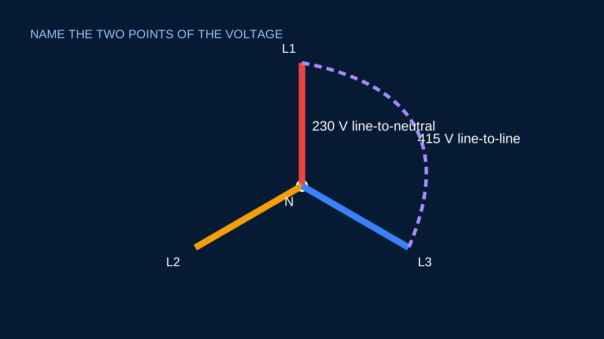
“The voltage is 415 V” is incomplete unless the measurement points are understood. In a three-phase four-wire system, voltage between two line conductors is line-to-line voltage. Voltage between one line and neutral is line-to-neutral voltage.
For an ideal balanced system:
VLL = √3 × VLN
If line-to-line voltage is 415 V, the ideal line-to-neutral magnitude is about 415 / 1.732 = 239.6 V.
Which value belongs in the current formula?
The common balanced three-phase expression is:
P = √3 × VLL × IL × PF
It expects line-to-line voltage. If you enter line-to-neutral voltage, the current result will be too high by a factor of √3.
A single-phase line-to-neutral load uses its actual terminal voltage in P = V × I × PF; no extra √3 factor is added.
Voltage across the equipment phase
Connection changes the voltage experienced by each load phase. In star, each phase is connected line to star point, so its phase voltage is the line-to-neutral magnitude for a balanced system. In delta, each phase is connected across two lines and sees line-to-line voltage.
That distinction matters for motor windings, heater elements and transformer connections. The supply description alone does not show how the internal phase is connected.
Nominal and measured voltage
Nominal voltage is a system designation. The voltage at a load can differ because of source regulation, conductor drop, transformer tap position and changing load. Use nominal values for a clearly labelled preliminary estimate. Use measured values from the same operating condition when assessing actual performance.
Do not combine measured current from one phase with a voltage taken at a different time or point and expect a high-quality power estimate.
A checklist before calculation
- Identify the two points between which voltage is defined.
- Confirm whether the load is single phase or balanced three phase.
- Confirm star, delta or another equipment connection where phase quantities matter.
- Label the value
VLLorVLNin notes and schedules. - Use the formula written for that voltage definition.
The arithmetic is short. Most errors happen one step earlier, when the correct number is attached to the wrong voltage label.
Start with two named points
Voltage is always a difference between two points. “The voltage is 230 V” is incomplete until the reference point is known. VLN is measured between a line conductor and neutral. VLL is measured between two line conductors. A meter does not know which system diagram you intended; it only reports the potential difference across its probes.
In a balanced star system, the three phase-to-neutral voltage vectors are separated by 120°. Subtracting one from another gives a line-to-line magnitude √3 times larger. This is the origin of the familiar relationship VLL = √3 × VLN.
A 415/240 V example
For a nominal 415 V line-to-line supply, the corresponding phase voltage is:
VLN = 415 ÷ √3 = 239.60 V
That is commonly discussed as 240 V. If a single-phase branch uses line and neutral, 240 V is the relevant nominal value. If a balanced three-phase load uses all three lines, 415 V is the value used with the standard line-current power formula.
Entering 240 V into P = √3 × VLL × IL × PF would understate power or overstate current. Entering 415 V into P = VLN × I × PF for a single-phase branch would make the opposite kind of error.
Star, delta and equipment terminals
The system supply description does not automatically reveal the voltage across every internal winding. In star, each winding is connected from a line to the star point and sees phase voltage. In delta, each winding is connected between two lines and sees line voltage.
Motor and transformer nameplates may show two permissible voltage/connection combinations. Follow manufacturer instructions; never infer link placement from a generic worked example. The purpose of the relationship is to interpret a known connection, not to choose one blindly.
Measurement and documentation habits
Before measuring, use appropriate procedures, equipment ratings and competent personnel. Record the two points, not merely the number: “L1–L2 = 412 V” or “L1–N = 238 V”. On a three-phase supply, record all relevant line-to-line and line-to-neutral values if balance matters.
In drawings and calculation notes, use explicit labels such as 415 V VLL and 240 V VLN. That small addition makes calculator inputs reviewable and prevents a factor-of-√3 mistake from surviving into cable, transformer or protection calculations.
Sources and limits
Preliminary engineering aid only. Voltage measurement exposes hazardous conductors and must be performed only with suitable equipment, procedures and competence.
Verify applicable laws, standards, manufacturer data and project conditions with a qualified electrical professional before construction, procurement or regulatory submission.
CONTINUE READING
Related articles
Power and current
Why √3 appears in three-phase power calculations
The √3 factor is geometry, not a memorised correction. It connects phase quantities with line quantities in a balanced system.
Power and current
Line current and phase current are not always the same
In star, line current matches winding current. In delta, the balanced line current is √3 times the phase-branch current.
Power and current
Balanced three-phase current: the preliminary calculation
A transparent explanation of the familiar √3 relationship, the voltage that belongs in it and the conditions under which it is useful.