
Power and current
Why √3 appears in three-phase power calculations
The √3 factor is geometry, not a memorised correction. It connects phase quantities with line quantities in a balanced system.
Open the three-phase current calculator →Published 26 September 2026

It comes from vector geometry
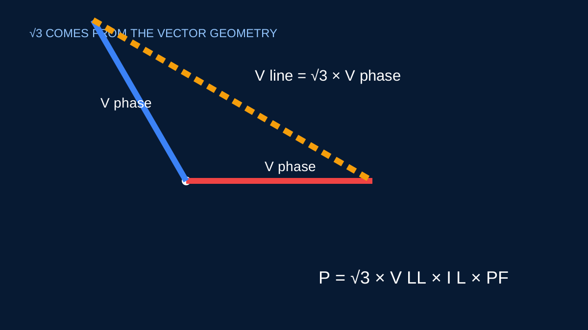
Three phase voltages are separated by 120 electrical degrees. A line-to-line voltage is the vector difference between two phase-to-neutral voltages. Because those vectors point in different directions, ordinary subtraction does not apply.
For equal phase-voltage magnitudes Vph, the vector difference has magnitude:
VLL = √3 × Vph
and is shifted by 30° relative to the associated phase voltage. The √3 factor is approximately 1.73205.
From per-phase power to total power
For one phase of a balanced load, active power is Pph = Vph × Iph × PF. Across all three phases:
Ptotal = 3 × Vph × Iph × PF
In a star-connected load, line current equals phase current and Vph = VLL / √3. Substitute that relationship:
Ptotal = 3 × (VLL / √3) × IL × PF
Since 3 / √3 = √3:
Ptotal = √3 × VLL × IL × PF
The standard balanced three-phase formula is therefore the per-phase sum rewritten using line quantities that are commonly measured.
Why the voltage definition matters
If the supply is described as 415 V three phase, that generally refers to line-to-line voltage. The corresponding nominal phase-to-neutral value is around 240 V in the ideal geometric relationship. Using 240 V in the line-voltage formula introduces a √3 error.
Conversely, using 415 V in a per-phase formula without the correct connection relationship also produces the wrong answer. Write VLL or Vph beside the value rather than leaving voltage unlabeled.
Star and delta do not remove the geometry
In star, line current equals phase current while line voltage is √3 times phase voltage. In delta, line voltage equals phase voltage while line current is √3 times phase current for a balanced load. The total-power expression in line quantities is the same.
That does not mean line and winding currents are interchangeable. Equipment winding current, conductor line current and protective-device current must be identified at the correct point.
Limits of the familiar formula
The derivation assumes balanced sinusoidal quantities. Significant unbalance requires phase-by-phase or symmetrical-component analysis. Distorted waveforms require power measurement or analysis that accounts for harmonic components.
Understanding where √3 comes from makes it easier to spot a wrong voltage or current definition before a calculator turns it into a confident-looking result.
Deriving the voltage relationship
Take two equal phase-to-neutral voltage vectors separated by 120°. Line-to-line voltage is the difference between those vectors. Applying the cosine rule gives:
VLL² = VLN² + VLN² − 2 × VLN × VLN × cos(120°)
Because cos(120°) = −0.5, the expression becomes:
VLL² = 3 × VLN²
and therefore VLL = √3 × VLN. With 230 V line-to-neutral, the ideal line-to-line value is about 230 × 1.732 = 398 V. A nominal system may be described as 400/230 V or 415/240 V, so use the actual nominated or measured values rather than manufacturing a voltage from a rounded ratio.
Deriving the power relationship
For a balanced load, total real power is three times the real power in one phase:
P = 3 × Vphase × Iphase × PF
In a star-connected load, Iline = Iphase and Vphase = VLL ÷ √3. Substitute those relationships:
P = 3 × (VLL ÷ √3) × Iline × PF
which simplifies to P = √3 × VLL × Iline × PF. The compact formula is therefore not an extra allowance or empirical multiplier. It is the three-phase total expressed in line quantities.
Why delta still reaches the same line formula
In a balanced delta connection, phase voltage equals line voltage, while line current is √3 times phase current. Substitution again produces P = √3 × VLL × Iline × PF. The internal winding relationships differ, but the total balanced power expressed through line voltage and line current has the same form.
This distinction matters when comparing a motor winding current with a feeder line current. Do not assume the current through one delta winding equals the current measured in a line conductor.
A quick error check
For 10 A at 415 V and unity power factor, balanced apparent power is about 7.19 kVA. If a calculation returns 4.15 kVA, the √3 factor was probably omitted. If it returns roughly 12.45 kVA, √3 may have been applied twice.
These checks are useful, but they depend on balanced sinusoidal conditions. For a visibly unbalanced or distorted load, measure or calculate each phase with a method suited to the waveform and connection.
Sources and limits
Preliminary engineering aid only. The explanation assumes a balanced sinusoidal system and does not cover unbalanced sequence components or harmonic power.
Verify applicable laws, standards, manufacturer data and project conditions with a qualified electrical professional before construction, procurement or regulatory submission.
CONTINUE READING
Related articles
Power and current
Balanced three-phase current: the preliminary calculation
A transparent explanation of the familiar √3 relationship, the voltage that belongs in it and the conditions under which it is useful.
Power and current
Line-to-line and line-to-neutral voltage, without the usual confusion
A three-phase voltage needs a reference: between two lines, or from one line to neutral. The formulas cannot decide that for you.
Power and current
Line current and phase current are not always the same
In star, line current matches winding current. In delta, the balanced line current is √3 times the phase-branch current.