
Voltage drop and conductors
How far can this cable run before voltage drop exceeds the target?
Maximum route length is an inverse voltage-drop calculation, not a complete cable-sizing decision.
Open the maximum cable length calculator →Published 26 September 2026

Turning the usual calculation around
A normal voltage-drop calculation starts with route length and returns volts dropped. Sometimes the useful question is the reverse: with this current, conductor data and drop target, how long can the route be?
The algebra is simple, but the result remains tied to every input assumption. A maximum length calculated from the wrong circuit geometry is still wrong.
Worked mV/A/m example
Take a 230 V circuit carrying 10 A. The selected voltage-drop target is 3%, so the voltage allowance is:
ΔVtarget = 230 × 3 / 100 = 6.9 V
If the phase-specific conductor value is 10 mV/A/m:
L = 6.9 × 1,000 / (10 × 10) = 69 m
The answer is a one-way source-to-load route length. It does not mean 69 m of total copper, nor does it approve that conductor for the load.
R/X data and power factor
With resistance and reactance data, the effective impedance term changes with power factor. For balanced three phase:
Lkm = ΔVtarget × parallel runs / [√3 × I × (R cosφ + X sinφ)]
The calculator converts the final distance to metres. DC and single-phase formulas use their applicable circuit geometry. A zero or negative effective impedance is rejected rather than returning an infinite or misleading route length.
Parallel runs
The simplified model divides effective impedance by the number of equal parallel paths. Two identical, equally sharing runs therefore double the voltage-drop-limited distance compared with one run. Real current sharing depends on matched conductors, routing, terminations and installation symmetry, so this is an engineering assumption that must be checked.
What can govern before voltage drop
A route may be shorter than the calculated limit and still need a larger cable because of:
- corrected current-carrying capacity;
- fault thermal requirements;
- protective-device operation;
- starting or transient voltage performance;
- installation method and ambient conditions;
- termination and mechanical constraints.
Use the maximum-length result during route comparison or early planning. Once a route and candidate cable are known, run the forward voltage-drop calculation and complete the other cable and protection checks with traceable data.
Work backwards without losing the geometry
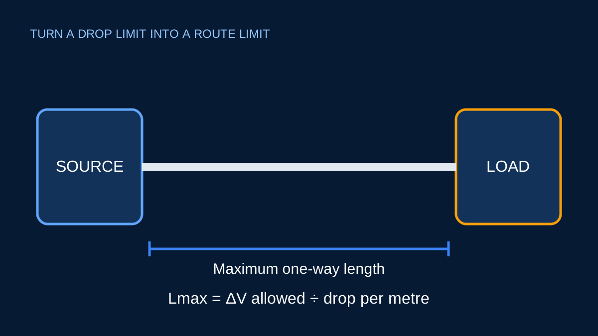
The inverse calculation is only as sound as the forward formula it reverses. In mV/A/m mode, a 230 V single-phase circuit, 10 A current, 3% target and 10 mV/A/m coefficient gives an allowed drop of 230 × 0.03 = 6.9 V. The maximum one-way length is:
Lmax = (6.9 × 1000) ÷ (10 × 10) = 69 m
That answer assumes the coefficient already represents the relevant circuit arrangement. Do not add another factor of two just because the physical circuit has an outgoing and return conductor. The geometry should already be embodied in the selected mV/A/m figure.
With R/X data, the geometry factor appears explicitly: two for DC or single phase, and √3 for balanced three phase. Resistance and reactance must be in ohms per kilometre, while the output route is converted back to metres. Writing the unit conversion in the trace is an effective defence against answers that are wrong by a factor of 1,000.
Parallel paths need one consistent treatment
If two equal parallel runs share current evenly, the equivalent impedance is half that of one run. The maximum route length therefore doubles in the ideal model. The same result can be reached by halving current in each cable, but the calculation must not halve both current and impedance. Doing both would count the benefit twice and predict four times the route length.
Equal sharing depends on identical conductor material, size, length, route, termination and impedance. A clean numeric output does not verify those physical conditions. Record “equal current sharing assumed” with the result and review whether paralleling is permitted and practical for the proposed installation.
A maximum is not a recommended working length
The result marks the point where the selected drop target is reached for the stated load. It contains no allowance for source-voltage variation, future load growth, motor starting, conductor-temperature uncertainty or imperfect current sharing. Design practice may therefore select a shorter route, a larger conductor or a tighter target.
After a route is selected, reverse the workflow: enter the actual length into the forward voltage-drop calculator, keep the same data source, and compare the resulting voltage at the load with equipment needs. Then complete ampacity, short-circuit, protection, mechanical and installation checks independently.
Sources and limits
Preliminary engineering aid only. The route limit addresses only the selected voltage-drop model and does not establish cable ampacity, fault performance or installation suitability.
Verify applicable laws, standards, manufacturer data and project conditions with a qualified electrical professional before construction, procurement or regulatory submission.
CONTINUE READING
Related articles
Voltage drop and conductors
Voltage drop: route length, conductor data and useful checks
Voltage drop is easy to calculate badly. The important work is choosing matching conductor data, geometry and route length.
Voltage drop and conductors
What an mV/A/m value includes—and what it does not
mV/A/m is a compact voltage-drop coefficient. Its convenience depends on using the value for the exact circuit arrangement it represents.
Voltage drop and conductors
One-way route length versus total conductor length
Length errors often come from counting the return path twice. Start by identifying the geometry built into the selected formula or coefficient.