
Voltage drop and conductors
A three-phase voltage-drop calculation, worked from start to finish
A substituted example shows where √3, route length, resistance, reactance and power factor enter the result.
Open the voltage-drop calculator →Published 26 September 2026

Define the case
Consider a balanced three-phase load with these preliminary inputs:
- line-to-line voltage: 415 V;
- line current: 20 A;
- power factor: 0.80;
- one-way route length: 50 m, or 0.05 km;
- resistance: 1.00 Ω/km;
- reactance: 0.08 Ω/km;
- one cable run per phase.
The conductor values are illustrative. A real calculation should use traceable data for the actual cable, temperature and arrangement.
Substitute the R/X formula
For balanced three phase:
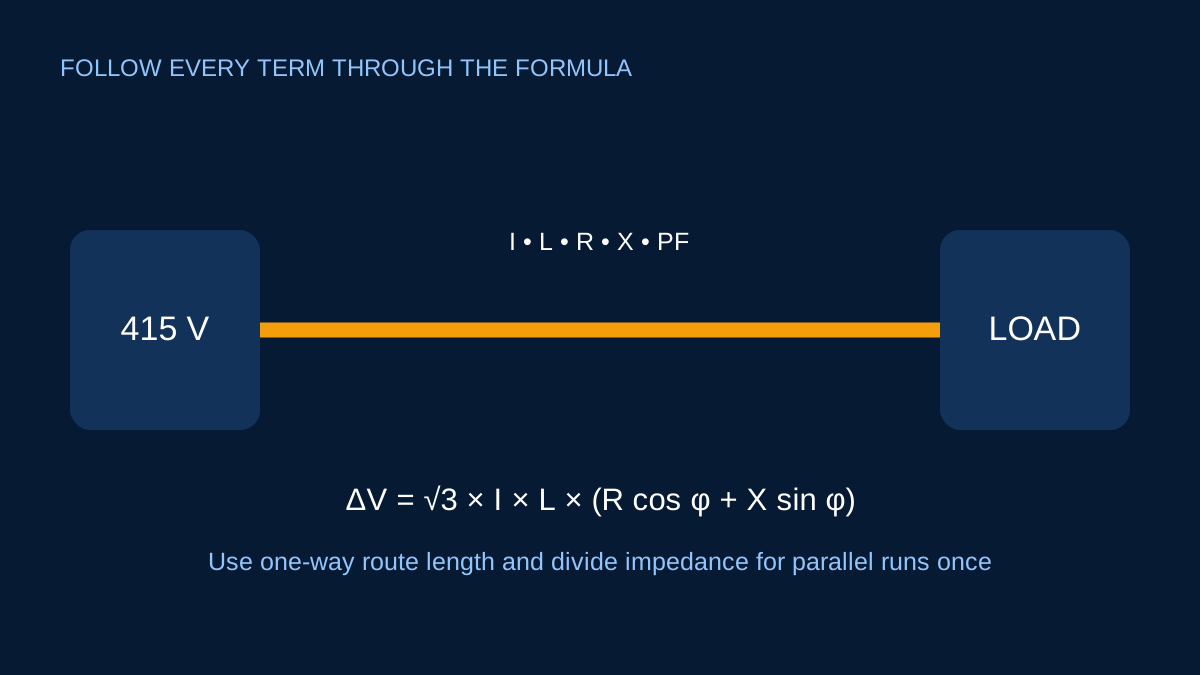
ΔV = √3 × I × L × (R cosφ + X sinφ)
Power factor gives cosφ = 0.80, so:
sinφ = √(1 − 0.80²) = 0.60
Now substitute:
ΔV = 1.73205 × 20 × 0.05 × (1.00×0.80 + 0.08×0.60)
ΔV = 1.469 V
Percentage drop is:
1.469 / 415 × 100 = 0.354%
Estimated end voltage is approximately 415 − 1.469 = 413.53 V under the simplified steady-state assumptions.
Why reactance appears
In AC circuits, conductor impedance includes resistance and reactance. Their contributions to the in-phase voltage change depend on load power factor. Ignoring reactance may be acceptable for some preliminary short routes and conductor arrangements, but it should not be silently set to zero when traceable data says otherwise.
Route length and parallel runs
The 50 m is the physical source-to-load distance. The three-phase geometry is already represented by √3. Entering 100 m to represent an imagined return path would double the result incorrectly.
If two identical equal-sharing runs are used per phase, the simplified impedance contribution is divided by two once. Installation symmetry and current sharing must still be reviewed.
Compare with a chosen target carefully
A calculator can compare 0.354% with a target entered by the user. It cannot decide which target is legally or technically appropriate for every installation. Equipment starting, source variation and terminal voltage requirements may lead to a stricter project objective.
Finally, a small voltage-drop percentage does not establish cable suitability. Corrected ampacity, fault performance, protection and installation conditions remain independent checks.
The worked R/X calculation
Take a balanced 415 V circuit carrying 20 A over a 50 m one-way route. Assume conductor data of R = 1.00 Ω/km and X = 0.08 Ω/km at the stated operating basis, with PF 0.80.
The sine component is sin φ = √(1 − 0.80²) = 0.60. Convert length to kilometres and substitute:
ΔV = √3 × 20 × 0.05 × (1.00 × 0.80 + 0.08 × 0.60)
ΔV = 1.469 V
Percentage drop is 1.469 ÷ 415 × 100 = 0.354%, and the estimated load-end voltage is about 413.53 V. Keeping the intermediate R cos φ and X sin φ terms visible makes unit and PF errors easier to find.
What changes with parallel runs
With two equal parallel runs, equivalent R and X are divided by two, so the ideal voltage drop halves to about 0.735 V. Do not also divide the entered total circuit current: that would apply the sharing benefit twice.
This simplification assumes identical paths and equal sharing. Differences in conductor length, termination resistance, routing or grouping can disturb the balance. The calculation result should therefore retain the equal-sharing assumption.
Temperature and data provenance
Resistance rises with conductor temperature. If the 1.00 Ω/km figure is stated at 20°C but the conductor operates much warmer, using it unchanged may understate voltage drop. Prefer reviewed cable data at an appropriate temperature, or make a transparent temperature adjustment when the source basis supports it.
Reactance also depends on cable construction and arrangement. Do not transplant an R/X pair from a different product or geometry because the cross-sectional area looks similar. Record manufacturer, document, table, temperature and configuration beside the entered values.
Check motor-start and terminal needs separately
The steady 20 A calculation does not describe a motor start or another temporary high-current event. A circuit with a small running drop can experience a much larger transient drop. Equipment minimum terminal voltage and source impedance may govern the real design question.
Use this worked example to verify arithmetic and route geometry. For an actual circuit, pair the result with operating scenarios, corrected ampacity, fault-loop and protective-device checks, and the applicable project requirements.
Sources and limits
Preliminary engineering aid only. The example uses illustrative custom conductor data and a user-selected target; it is not a cable recommendation or code limit.
Verify applicable laws, standards, manufacturer data and project conditions with a qualified electrical professional before construction, procurement or regulatory submission.
CONTINUE READING
Related articles
Voltage drop and conductors
Voltage drop: route length, conductor data and useful checks
Voltage drop is easy to calculate badly. The important work is choosing matching conductor data, geometry and route length.
Voltage drop and conductors
Resistance, reactance and power factor in AC voltage drop
R and X do not contribute identically to the in-phase voltage change. Power factor sets the weighting in the common approximation.
Voltage drop and conductors
One-way route length versus total conductor length
Length errors often come from counting the return path twice. Start by identifying the geometry built into the selected formula or coefficient.