
Voltage drop and conductors
One-way route length versus total conductor length
Length errors often come from counting the return path twice. Start by identifying the geometry built into the selected formula or coefficient.
Check voltage drop with one-way length →Published 26 September 2026

Two lengths can describe the same circuit
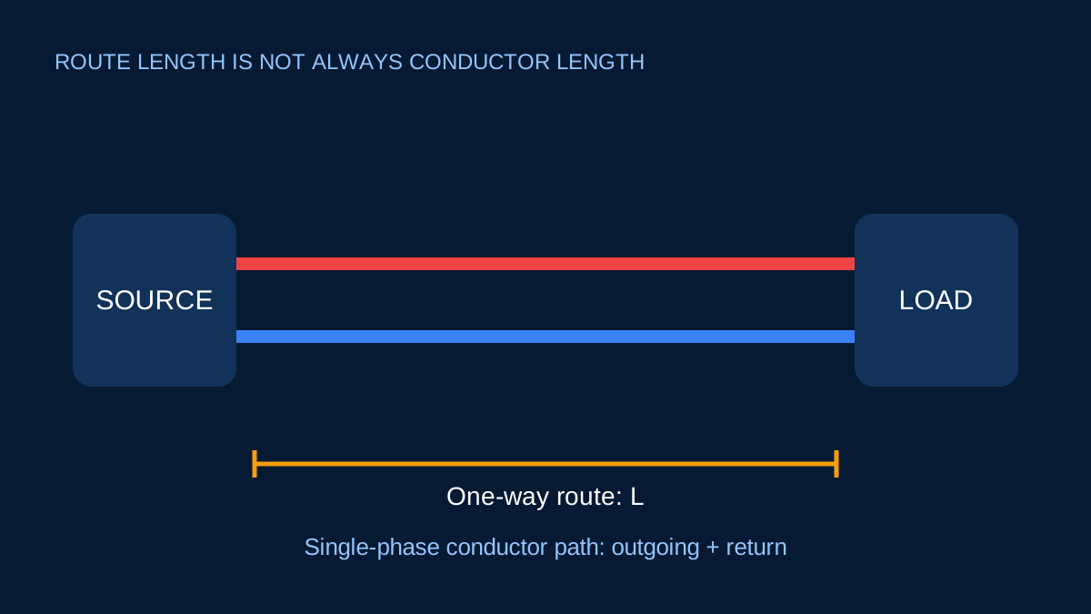
Imagine a load 40 m from its source. The physical one-way route is 40 m. In a two-wire circuit, there may be approximately 80 m of current-carrying conductor in the outgoing and return paths.
Both statements can be true. The correct input depends on the formula.
A single-phase R calculation
If R is resistance per conductor per kilometre and L is the one-way route, a simplified single-phase resistive drop uses:
ΔV = 2 × I × L × R
The factor 2 accounts for outgoing and return conductors. Entering 80 m as L while leaving the factor 2 in place counts the path twice.
For 10 A, 40 m and 1 Ω/km:
ΔV = 2 × 10 × 0.04 × 1 = 0.8 V
Using 80 m incorrectly would return 1.6 V.
Three-phase geometry is different
A balanced three-phase R/X calculation typically uses the one-way route with a √3 geometry factor. It does not use a simple “out and back” factor of two. The phase currents and voltages are vector quantities.
This is another reason not to move a memorised length convention from one formula into another.
mV/A/m needs its source definition
A phase-specific mV/A/m coefficient commonly incorporates the applicable circuit arrangement. ElectricalDyev multiplies that value by load current and one-way route length. Do not add an extra factor unless the source explicitly defines the coefficient differently.
Route measurements still need judgement
Measure the actual intended path, including vertical rises, diversions and termination allowances when appropriate to the design stage. A straight-line distance on a plan can understate installed length. Conversely, adding generous allowance without documenting it can obscure what the result represents.
For parallel runs, use the same route definition for each path and confirm that conductor lengths and terminations support equal sharing.
Write the convention beside the number
Record “one-way source-to-load route” or “total conductor length” explicitly in calculations and schedules. Also record whether conductor impedance is per conductor, per loop or already adjusted for a circuit arrangement.
Once those labels are visible, a reviewer can check the geometry. Without them, even a perfectly evaluated equation may be using the wrong distance.
Why formulas use length differently
A simplified single-phase resistive circuit has an outgoing conductor and a return conductor. If L is the one-way route, the total resistive path is represented by 2L, so the voltage-drop expression contains a factor of two.
Balanced three-phase line-to-line drop is commonly written with √3 × L when L is the one-way route and conductor impedance is given per conductor. The geometry is different from a two-wire loop. Copying the single-phase factor into a three-phase formula double-counts the return concept.
An mV/A/m value may already package the relevant geometry. In that case, enter the one-way route defined by the data source and do not bolt on another two or √3 unless the source explicitly requires it.
A 30 m example
Imagine a distribution board 30 m from a single-phase load along the intended route. The one-way route length is 30 m. The project may require about 60 m of current-carrying conductor before allowing for bends, terminations and waste, but the voltage-drop formula may still take L = 30 m and include its own factor of two.
If someone enters 60 m into that formula, the calculated drop doubles. If the same person also uses an mV/A/m coefficient that includes loop geometry, the error may be compounded. A simple sketch showing source, load and the definition of L prevents this more effectively than extra decimal precision.
Route length is not purchase quantity
Procurement length can include vertical rises, offsets, slack, termination tails, drum constraints and spare allowance. Those are legitimate planning needs, but they should not be silently substituted for the electrical route basis. Keep “electrical one-way route”, “estimated installed conductor” and “purchase quantity” as distinct fields.
For multicore cable, one metre of cable contains multiple conductors. Counting each core as a separate metre may be useful for material accounting but does not change the source-to-load route length.
Questions to ask before accepting a length
Ask where the route begins and ends, how the length was measured, whether it is horizontal-only or true installed route, and whether the formula expects one-way, loop or per-phase length. Then check the impedance unit—Ω/km, Ω/m or a packaged mV/A/m figure.
This disciplined naming also helps with maximum-length calculations. An inverse result should be labelled “maximum one-way route under the entered drop model”, not “maximum cable required” or “approved circuit length”.
Sources and limits
Preliminary engineering aid only. Always follow the length definition supplied with the conductor data or formula; incompatible conventions can double or halve the result.
Verify applicable laws, standards, manufacturer data and project conditions with a qualified electrical professional before construction, procurement or regulatory submission.
CONTINUE READING
Related articles
Voltage drop and conductors
Voltage drop: route length, conductor data and useful checks
Voltage drop is easy to calculate badly. The important work is choosing matching conductor data, geometry and route length.
Voltage drop and conductors
What an mV/A/m value includes—and what it does not
mV/A/m is a compact voltage-drop coefficient. Its convenience depends on using the value for the exact circuit arrangement it represents.
Voltage drop and conductors
Parallel cable runs: what changes in a voltage-drop calculation
Two identical paths can halve effective impedance in a simple model. Unequal paths do not automatically share current equally.