
Power and current
How much kVAr is needed to improve power factor?
The kVAr formula is straightforward. Choosing equipment safely still requires harmonic, resonance and switching studies.
Open the power-factor correction calculator →Published 26 September 2026

What correction is trying to change
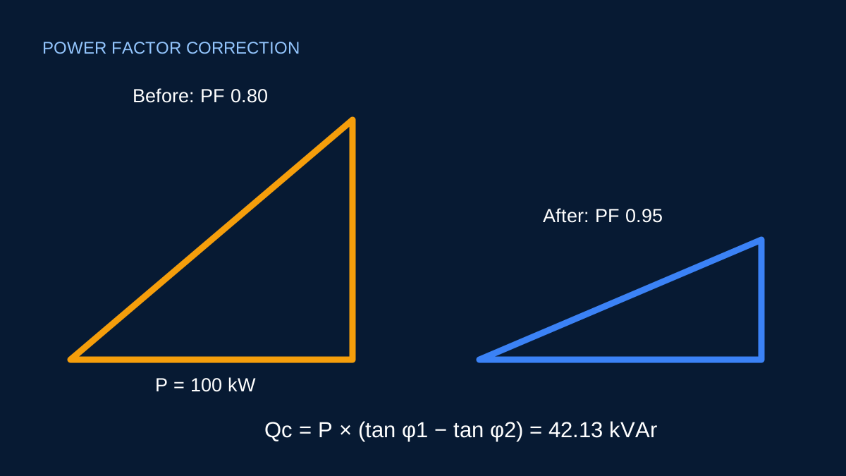
An inductive AC load can draw current that does not contribute to active work but is still carried by conductors and upstream equipment. Power-factor correction supplies part of that reactive requirement locally. The active power in kW remains the same while apparent power and line current can fall.
The preliminary correction requirement is:
Qc = P × [tan(cos⁻¹ PF1) − tan(cos⁻¹ PF2)]
PF1 is the existing power factor and PF2 is the target.
Worked example: 100 kW from 0.80 to 0.95
At 0.80 power factor, the tangent of the phase angle is 0.75. At 0.95, it is about 0.3287.
Qc = 100 × (0.75 − 0.3287) = 42.13 kVAr
On a balanced 415 V three-phase system, the current falls from approximately:
100,000 / (√3 × 415 × 0.80) = 173.90 A
to:
100,000 / (√3 × 415 × 0.95) = 146.44 A
This comparison assumes the same active power and steady sinusoidal operation.
Target power factor is a design choice
The calculator does not impose a target. Commercial tariffs, utility arrangements, equipment behavior and the installation’s operating profile can all influence a reasonable objective. Chasing exactly 1.00 is not automatically best and can create leading power-factor conditions when loads switch off.
Measured power factor should come from a representative operating period. A lightly loaded motor can behave differently from the same motor near rated load. One reading may not represent a full shift or production cycle.
Why kVAr does not select the equipment
A practical capacitor installation may use staged switching, automatic control, contactors, detuning reactors or harmonic filtering. Capacitor voltage rating, discharge arrangements, enclosure, ventilation and fault protection also matter.
Harmonics can interact with capacitance and system inductance. Resonance can amplify current or voltage instead of improving the installation. That is why the calculator stops at a preliminary reactive-power requirement.
Use the output responsibly
Record the active power, measured power-factor range, voltage and load pattern. Use the result to frame a power-quality discussion, not to order a bank from kVAr alone. A suitable study should examine the actual waveform, switching states and network characteristics before equipment is selected.
Separate a target from a promise
A target such as 0.95 is a calculation input, not a universal rule. The appropriate target may be influenced by the utility arrangement, site operating profile, equipment, tariff structure and local requirements. Correcting all the way to unity is not automatically desirable: load can fall after a fixed capacitor is connected, leaving the installation with a leading power factor.
The calculator requires the target power factor to be higher than the existing value. If both values are equal, no additional kVAr is required by the ideal equation. If the target is lower, the request is not “correction” in the sense modelled here and the input is rejected rather than returning a negative bank size.
Check the 100 kW example by components
At 100 kW and PF 0.80, apparent power is 100 ÷ 0.80 = 125 kVA. The corresponding reactive power is 75 kVAr. At PF 0.95, apparent power falls to about 105.26 kVA and reactive power to about 32.87 kVAr. The difference is approximately 42.13 kVAr.
At 415 V balanced three phase, current changes from:
Ibefore = 100,000 ÷ (√3 × 415 × 0.80) = 173.90 A
to:
Iafter = 100,000 ÷ (√3 × 415 × 0.95) = 146.44 A
Real power has not decreased in this idealised example. The lower line current comes from reducing the reactive component of the current. Energy savings should not be claimed from that current comparison alone; losses and operating patterns require measurement.
Why a practical bank is a controls problem too
Loads vary. A single fixed correction value calculated from a peak snapshot may over-correct at light load and under-correct at another time. Automatic banks use stages and a controller so the connected kVAr can follow changing conditions. The number and size of stages influence resolution, switching frequency and maintenance.
Capacitors also interact with network inductance. Harmonic resonance, voltage rise, transient switching and capacitor-duty ratings need specialist attention. Variable-speed drives and other power-electronic loads make a harmonic survey especially important. The calculator deliberately stops before equipment selection because the ideal trigonometry cannot resolve those risks.
Sources and limits
Preliminary engineering aid only. The calculated kVAr is not a capacitor-bank specification and does not assess harmonics, resonance, switching transients or leading power factor.
Verify applicable laws, standards, manufacturer data and project conditions with a qualified electrical professional before construction, procurement or regulatory submission.
CONTINUE READING
Related articles
Power and current
Why current rises when power factor falls
Power factor changes current without changing the active kW requirement. A short table makes the effect easy to see.
Power and current
kW, kVA and kVAr: what each number tells you
These three quantities are related, but they answer different questions about an AC load and its effect on the supply.
Power and current
Balanced three-phase current: the preliminary calculation
A transparent explanation of the familiar √3 relationship, the voltage that belongs in it and the conditions under which it is useful.