
Voltage drop and conductors
Resistance, reactance and power factor in AC voltage drop
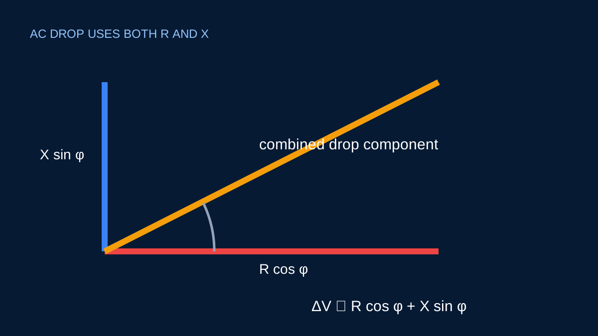
R and X do not contribute identically to the in-phase voltage change. Power factor sets the weighting in the common approximation.
Use the R/X voltage-drop mode →Published 26 September 2026

Resistance and reactance are different components
Resistance R is the in-phase component of impedance and produces real power loss. Reactance X is associated with stored electric or magnetic energy and contributes a quadrature component. Both are expressed in ohms, often normalised as ohms per kilometre for cable data.
For a common balanced three-phase approximation:
ΔV = √3 × I × L × (R cosφ + X sinφ)
with length in kilometres when R and X are in Ω/km.
Power factor sets the projection
Power factor gives cosφ. For a lagging 0.80 power factor, sinφ = 0.60. If R = 1.00 Ω/km and X = 0.08 Ω/km, the effective term is:
1.00×0.80 + 0.08×0.60 = 0.848 Ω/km
At a power factor closer to one, the resistance term has greater weighting and the reactance term less. The exact sign and treatment can depend on load behavior and the approximation being used, so the calculator states its assumptions.
Resistance changes with temperature
Cable resistance values may be supplied for a reference or operating temperature. Copper and aluminium both increase in resistance as temperature rises. Using a cold value for a hot conductor can understate voltage drop and losses.
Reactance is influenced by conductor geometry and spacing. Single-core cables arranged differently can have different inductive behavior even when material and cross-sectional area are the same.
Why mV/A/m cannot always reveal R and X
A combined mV/A/m coefficient can be convenient, but it may not expose the separate resistance and reactance contributions. That is enough for voltage drop when the coefficient matches the circuit. It is not enough to reconstruct resistive loss reliably.
R/X mode is preferable when you need the calculation trace to show both components or when load power factor is an explicit design variable.
Keep units compatible
A frequent error is multiplying metres directly by Ω/km without converting length. Fifty metres is 0.05 km. Another is entering milliohms as ohms. State units beside every source value and retain the source record.
The formula is a useful engineering approximation. Cable selection still requires corrected ampacity, fault performance, protection and installation review beyond the voltage-drop result.
Split the impedance into useful components
Resistance contributes in phase with current and is strongly affected by conductor material, cross-section and temperature. Reactance comes from the alternating magnetic field and depends on conductor arrangement, construction and frequency. In an AC voltage-drop approximation, power factor determines how those components project onto the load-voltage direction.
For a lagging load, the common component is R cos φ + X sin φ. At PF 0.80, cos φ = 0.80 and sin φ = 0.60. If R = 0.50 Ω/km and X = 0.08 Ω/km, the combined term is 0.50 × 0.80 + 0.08 × 0.60 = 0.448 Ω/km.
When reactance matters more
For smaller low-voltage conductors, resistance often dominates. As conductor size increases or arrangements change, resistance falls while reactance may not fall in the same proportion. Long high-current routes can therefore require both values even when a rough resistive estimate appeared adequate.
Do not assume one generic reactance value suits every single-core spacing, multicore cable or bus arrangement. Use data that identifies the construction and geometry. If the source gives impedance magnitude only, it cannot be separated into loss-producing resistance and reactive contribution without additional information.
A unit-safe worked substitution
For a balanced three-phase circuit at 50 A over 80 m, using the combined 0.448 Ω/km term:
ΔV = √3 × 50 × (80 ÷ 1000) × 0.448
ΔV = 3.104 V
At 415 V that is about 0.748%. Writing 80 ÷ 1000 visibly is worthwhile. Many spreadsheet errors come from hiding the metres-to-kilometres conversion inside an unexplained constant.
Leading and distorted loads need care
The sign of the reactive term can differ for a leading load, and voltage rise can occur in some conditions. The current calculator is intentionally framed for ordinary lagging or resistive preliminary assessments. It should not be used as a complete network-voltage model.
Harmonic currents see frequency-dependent impedance. A single fundamental R/X pair and one power factor cannot describe the resulting waveform drop. Use an appropriate power-quality or network study when nonlinear loads are material.
Sources and limits
Preliminary engineering aid only. Use traceable impedance values for the actual cable arrangement and frequency; the simplified expression is not a complete network study.
Verify applicable laws, standards, manufacturer data and project conditions with a qualified electrical professional before construction, procurement or regulatory submission.
CONTINUE READING
Related articles
Voltage drop and conductors
A three-phase voltage-drop calculation, worked from start to finish
A substituted example shows where √3, route length, resistance, reactance and power factor enter the result.
Voltage drop and conductors
Why conductor temperature changes resistance and voltage drop
A cable’s resistance is not fixed at every temperature. Load and installation conditions influence the value used in voltage-drop and loss estimates.
Voltage drop and conductors
What an mV/A/m value includes—and what it does not
mV/A/m is a compact voltage-drop coefficient. Its convenience depends on using the value for the exact circuit arrangement it represents.