
Protection and project workflow
Transformer Percentage Impedance and Fault Current: A Worked Estimate
A percentage impedance can turn rated current into a rough terminal-fault estimate, but source and circuit impedances change the real result.
Find transformer full-load current first →Published 10 October 2026

Start with the nameplate quantity, then the assumption
Transformer percentage impedance describes the voltage needed to drive rated current through the transformer under a defined short-circuit test. In a simplified model, it also indicates how strongly the transformer itself limits a three-phase short circuit at its secondary terminals.
A quick relationship is Isc ≈ In / (Z% / 100), where In is rated secondary current and Z% is the transformer’s percentage impedance. This equation makes sense only with its assumptions attached. It treats upstream source impedance as negligible and places the fault at the transformer terminals. A real supply and any downstream conductors add impedance. Motors and other sources can add current. The full study can therefore differ substantially.
Use the transformer current calculator to obtain the nominal current part of the example. It does not calculate fault current or determine a breaker’s interruption duty.
A worked three-phase example
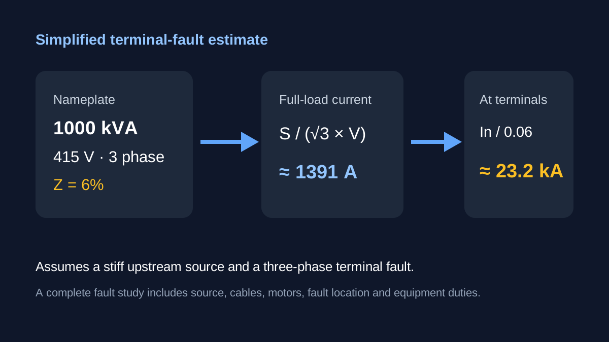
Assume a 1000 kVA three-phase transformer, nominal 415 V line-to-line on the secondary and 6% nameplate impedance. For this arithmetic illustration, use the nominal secondary voltage as the voltage basis. Confirm the manufacturer’s stated impedance and voltage basis before doing a project calculation.
First calculate rated secondary current:
In = S / (√3 × VLL)
In = 1,000,000 VA / (√3 × 415 V) ≈ 1391 A.
Convert six percent to a fraction: 6% / 100 = 0.06.
Now divide the nominal current by that fraction:
Isc ≈ 1391 A / 0.06 ≈ 23,190 A, or about 23.2 kA.
The result is a simplified prospective symmetrical three-phase current at the transformer secondary terminals. It is not current that will necessarily appear at the end of a feeder. It is also not a measured short-circuit value, a peak making current or an arc-flash result.
If the impedance were 5% with the same rating and voltage, the quotient would be approximately 1391 / 0.05 = 27.8 kA. Lower impedance in this simple model means a higher terminal fault-current estimate. That sensitivity is one reason guessing a “typical” percentage impedance is unsafe for equipment selection.
What changes when the fault moves away
A fault beyond a length of cable sees the transformer’s impedance plus relevant cable and source impedance. Resistance and reactance both matter, and they do not combine by simply adding their magnitudes. The prospective current generally decreases along a passive feeder as additional impedance is included. At the same time, motors, generators or other connected sources may contribute to a fault, especially in its early period.
The upstream utility system is not infinitely stiff. Its available fault level affects what appears at the transformer secondary. Multiple transformers operating in parallel change the network again. A precise calculation needs the actual one-line arrangement, voltage, equipment impedances and fault location.
The Schneider Electric Electrical Installation Guide distinguishes the simple transformer-terminal estimate from a short-circuit calculation at arbitrary points in a low-voltage installation. Keep that distinction when quoting the 23.2 kA figure.
Do not turn the estimate into a breaker choice
A protective device has a nominal current rating and a separate breaking or interrupting rating. The terminal fault-current estimate is only one possible input to the latter assessment. The actual duty at the device location, asymmetry, making capability, device standard, coordination and installation requirements all matter. The breaker current versus breaking-capacity article covers the distinction.
Percentage impedance can also influence voltage regulation and other transformer behaviour, but this article is limited to the fault-current relationship. Never use a simplified quotient to approve switchgear, conduct an arc-flash assessment or validate a protection scheme.
For a project record, note the transformer rating, secondary voltage, source of Z%, voltage basis, calculation point and every assumption. Calculate rated current as a first step, then obtain a complete fault study from a qualified electrical professional before equipment selection.
Sources and limits
Preliminary engineering aid only. The example assumes a stiff upstream source and a three-phase fault at the transformer terminals. It is not a protective-device breaking-capacity, arc-flash or installation fault study.
Verify applicable laws, standards, manufacturer data and project conditions with a qualified electrical professional before construction, procurement or regulatory submission.
CONTINUE READING
Related articles
Power and current
Transformer full-load current on the primary and secondary sides
A transformer keeps approximately the same apparent-power rating across both sides, but current changes as voltage changes.
Protection and project workflow
Breaker current rating is not breaking capacity
A 32 A breaker label tells you about nominal current. It does not say the device can interrupt every possible fault at that point.
Measurements and equipment
Why Transformers Are Rated in kVA Instead of kW
A transformer can supply different kW at different load power factors while the same kVA rating describes its voltage-and-current duty.