
Measurements and equipment
What Transformer Percentage Impedance on the Nameplate Means
The %Z printed on a transformer is not a voltage-drop target. It describes an impedance measurement at a defined test condition.
Try the transformer-only estimate →Published 25 October 2026
It is a property of this transformer, not a design target
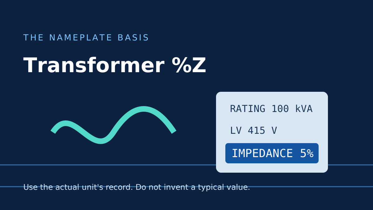
Percentage impedance, usually written %Z, is often near the voltage and kVA entries on a transformer nameplate. It is easy to mistake it for “the percentage voltage drop the installation may have.” It is not that. It is a transformer impedance value obtained under a defined short-circuit test, usually stated on the transformer’s rated basis.
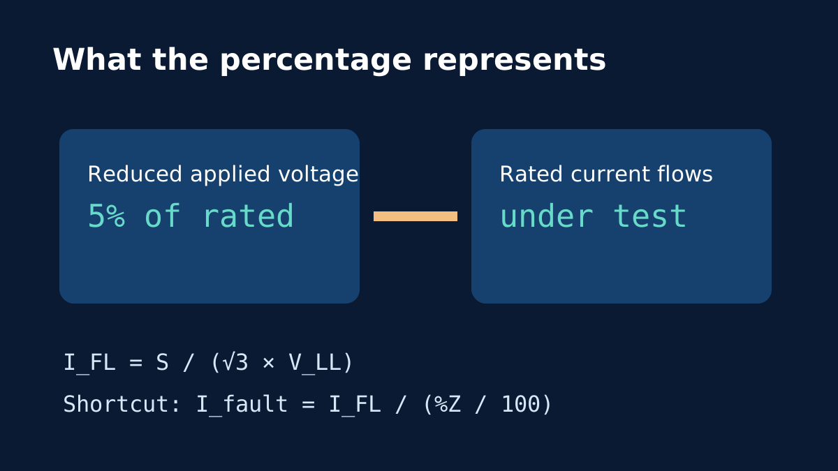
Eaton’s explanation describes the test idea: with the secondary shorted, the applied primary voltage is raised until rated secondary current flows. The ratio of that applied voltage to rated primary voltage, expressed as a percentage, is the transformer impedance. A real test belongs to competent personnel and controlled equipment—this explanation is not a procedure for carrying one out.
What the number does in a simple estimate
For a balanced three-phase transformer, nominal secondary full-load current is I_FL = S / (√3 × V_LL). Suppose the nameplate says 100 kVA, 415 V on the secondary and 5% impedance:
I_FL = 100,000 / (√3 × 415) = 139.12 A
In the transformer-only, unlimited-source shortcut, I_fault = I_FL / (5 / 100) ≈ 2,782 A, or 2.78 kA. Open the worksheet with this example. The result is a symmetrical RMS terminal arithmetic estimate, not a complete installation fault-current value.
Why not use a guessed “typical %Z”?
Changing 5% to 4% in the example increases the arithmetic result from roughly 2.78 kA to 3.48 kA. That sensitivity is why the worksheet requires the actual transformer record. Even the recorded nominal impedance can have manufacturing tolerance. The example is not a recommendation for either transformer.
The shortcut also leaves out upstream network impedance, voltage variation, motor or generator contribution, taps, downstream cables and non-three-phase faults. The source-assumption article explains why an unlimited-source result is not universally an upper bound for every equipment-duty question. Our existing impedance worked example develops the arithmetic further.
Keep the basis with the number
When recording %Z, attach the transformer identity, kVA base, voltage basis, source document and date. Do not copy a number from a different unit simply because its kVA looks similar. A qualified electrical professional needs the full project data to determine prospective fault levels, breaker interrupting duty, short-time withstand, protection coordination and applicable requirements.
Sources and limits
Preliminary engineering aid only. A nameplate percentage impedance and a shortcut calculation do not establish available fault current, device duty, protection settings or regulatory compliance.
Verify applicable laws, standards, manufacturer data and project conditions with a qualified electrical professional before construction, procurement or regulatory submission.
CONTINUE READING
Related articles
Protection and project workflow
Transformer Percentage Impedance and Fault Current: A Worked Estimate
A percentage impedance can turn rated current into a rough terminal-fault estimate, but source and circuit impedances change the real result.
Protection and project workflow
Transformer Fault Current: What the Infinite-Source Shortcut Leaves Out
Dividing full-load current by %Z is useful for understanding a transformer, but the available fault current at a board needs more information.
Power and current
Transformer full-load current on the primary and secondary sides
A transformer keeps approximately the same apparent-power rating across both sides, but current changes as voltage changes.