
Power and current
20 kW to amps at 415 V: a worked three-phase example
At 415 V three phase, 20 kW can mean several different line currents because operating power factor and efficiency matter.
Calculate 20 kW to amps →Published 26 September 2026

The short answer needs an assumption
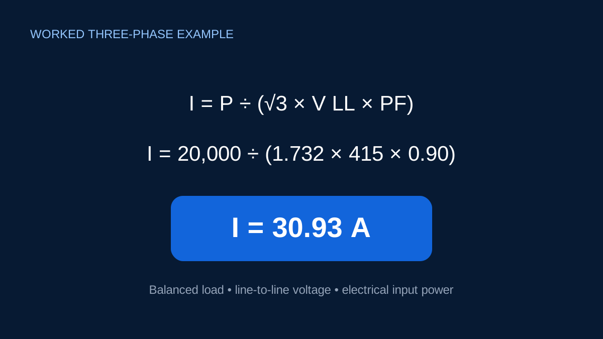
For a balanced three-phase active load, current is:
I = P / (√3 × VLL × PF)
At 20 kW, 415 V and power factor 0.80:
I = 20,000 / (1.73205 × 415 × 0.80) = 34.78 A
That is a valid arithmetic result for the stated assumptions. It is not a universal conversion for every 20 kW machine.
How power factor changes the answer
| Power factor | Calculated line current |
|---|---|
| 1.00 | 27.82 A |
| 0.90 | 30.92 A |
| 0.80 | 34.78 A |
| 0.70 | 39.75 A |
The active power remains 20 kW. Lower power factor increases apparent power and therefore line current. That extra current affects conductor loading and losses even though it does not represent additional active output.
What if 20 kW is motor shaft output?
The formula above treats 20 kW as electrical input. A motor nameplate may instead state mechanical output. At 90% efficiency, 20 kW shaft output needs approximately:
Pelectrical = 20 / 0.90 = 22.22 kW
At 415 V and 0.80 power factor, that becomes about 38.64 A. Applying efficiency in the wrong direction is a common mistake: electrical input is greater than mechanical output because losses must be supplied.
Check the voltage definition
The 415 V in this example is line-to-line voltage. The √3 relationship already accounts for the three-phase geometry. Do not replace it with a phase-to-neutral value while leaving the rest of the equation unchanged.
If the load is unbalanced, calculate or measure each phase rather than treating it as one balanced load. Drives and nonlinear equipment can also produce waveform effects that a simple sinusoidal formula does not capture.
Where to go after current
Use the calculated current as an input to a load schedule or preliminary voltage-drop assessment. Cable sizing still needs installation-specific ampacity, correction factors, fault checks and conductor data. Protection design must address fault current, breaking capacity and device behavior.
Writing the assumption beside the result—“20 kW electrical input, 415 V line-to-line, balanced three phase, PF 0.80”—is more useful than reporting “34.8 A” on its own.
Why power factor changes the answer
At unity power factor, the same 20 kW at 415 V would require:
I = 20,000 ÷ (√3 × 415 × 1.00) = 27.82 A
At PF 0.90 the current is 30.91 A, and at PF 0.80 it is 34.78 A. The active power delivered is unchanged in those comparisons. The extra current reflects a larger apparent-power requirement. This is why a current estimate copied without its power-factor assumption cannot be checked properly.
Do not choose whichever power factor produces a convenient answer. Use a value supported by the equipment nameplate, manufacturer data or measurement at a representative operating point. Motors and other loads can have different power factors at light load and rated load.
Electrical input versus mechanical output
The 20 kW in the worked example is electrical input. If 20 kW instead describes shaft output from a motor, efficiency belongs before the current calculation. With 90% efficiency, the estimated electrical input would be 20 ÷ 0.90 = 22.22 kW. At 415 V and PF 0.80, that becomes about 38.64 A rather than 34.78 A.
The difference is not a calculator preference; it is a difference in what the 20 kW label means. State whether the rating is electrical input, apparent power, or mechanical output before doing arithmetic. A motor nameplate should be read as a complete set of voltage, connection, current, output, efficiency and power-factor data.
What a clamp-meter comparison can tell you
Suppose the calculated steady current is 34.78 A but a clamp meter shows 24 A. That does not immediately prove an error. The machine may be lightly loaded, the real power may be below 20 kW, or the assumptions may not match the measurement point. Conversely, a higher reading could reflect overload, voltage variation, lower power factor, unbalance or a transient condition.
Measure all three phase currents when assessing a three-phase load. A single phase reading cannot demonstrate balance. Record voltage and operating state at the same time, and use a suitable power analyser when the actual kW, kVA, PF or harmonic content matters.
Rounding and design decisions
Keeping 34.78 A in a calculation trace is useful, but selecting a conductor or protective device is not a matter of rounding it to the nearest standard rating. Design current is only the start. Corrected cable capacity, voltage drop, fault protection, starting behaviour, device characteristics and applicable requirements remain separate decisions.
Sources and limits
Preliminary engineering aid only. The worked result is a steady balanced-load estimate and does not determine starting current, cable size or protective-device selection.
Verify applicable laws, standards, manufacturer data and project conditions with a qualified electrical professional before construction, procurement or regulatory submission.
CONTINUE READING
Related articles
Power and current
How to convert kW to amps for preliminary electrical work
A practical guide to the relationship between power, voltage, power factor, efficiency and line current.
Power and current
Why current rises when power factor falls
Power factor changes current without changing the active kW requirement. A short table makes the effect easy to see.
Power and current
Why √3 appears in three-phase power calculations
The √3 factor is geometry, not a memorised correction. It connects phase quantities with line quantities in a balanced system.