
Power and current
Transformer full-load current on the primary and secondary sides
A transformer keeps approximately the same apparent-power rating across both sides, but current changes as voltage changes.
Open the transformer current calculator →Published 26 September 2026
Why kVA is the starting point
Transformers are commonly rated in apparent power, expressed in kVA. The rating combines voltage and current without assuming a particular load power factor. That makes it suitable for finding nominal full-load current on each side.
For single phase:
I = S / V
For balanced three phase:
I = S / (√3 × VLL)
Use volt-amperes for S and volts for V. The result is amperes.
A 100 kVA example
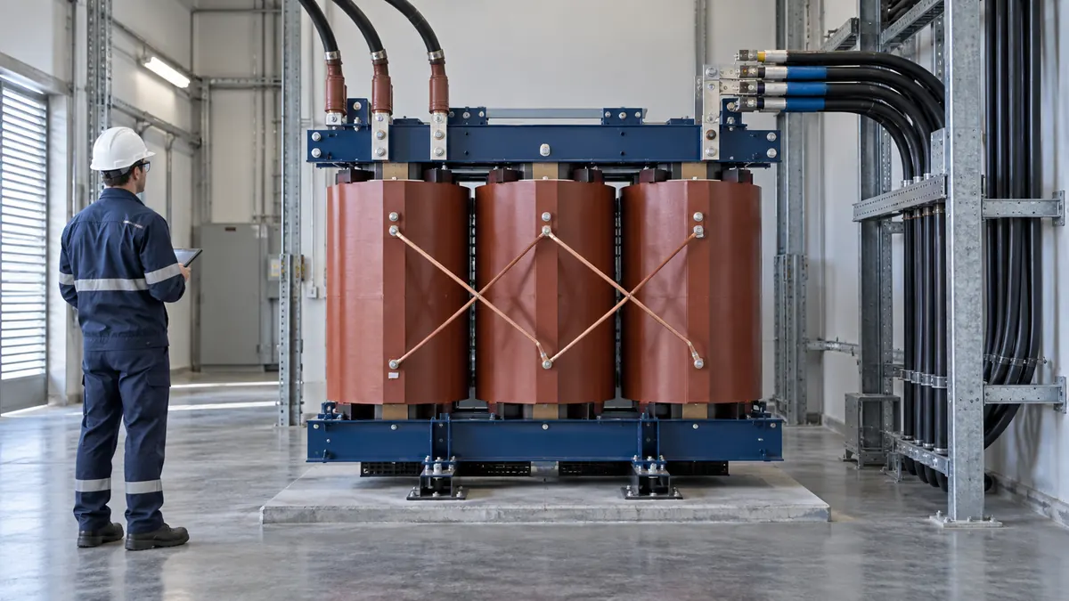
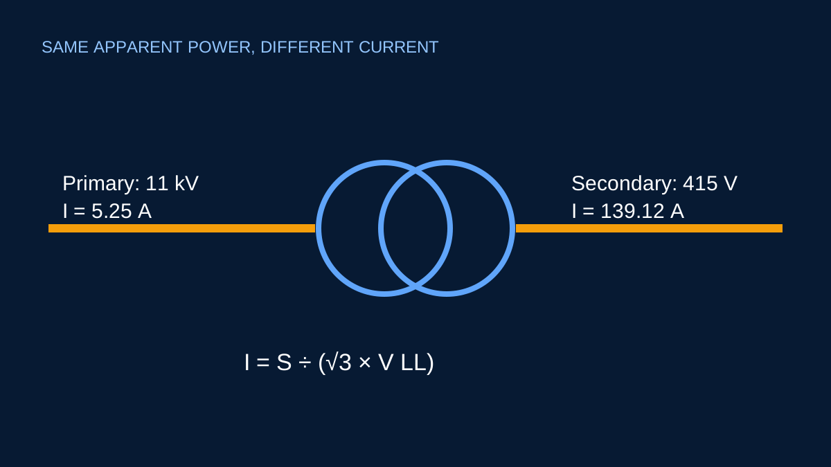
Consider a three-phase transformer rated 100 kVA, with an 11 kV primary and 415 V secondary.
Primary current:
I1 = 100,000 / (√3 × 11,000) = 5.25 A
Secondary current:
I2 = 100,000 / (√3 × 415) = 139.12 A
The large difference is expected. Apparent power is approximately transferred across the transformer while voltage and current trade places. A lower secondary voltage requires higher current for the same kVA.
What “full load” means here
The calculation uses the nameplate apparent-power rating and nominal voltages. It does not claim that the transformer is currently carrying that load. It also does not model internal losses or voltage regulation. Those effects matter in detailed studies, but they do not change the purpose of this first calculation: translating the rating into nominal current.
Tap settings and actual measured voltages may differ from the nominal values. If a measured operating current is being assessed, use the voltage and conditions from the same operating state rather than mixing them with unrelated nameplate figures.
Current is not enough to select protection
Transformer energisation can produce a large inrush current. Available fault current on the secondary depends on transformer impedance and the upstream system. Protection also needs to consider conductor capacity, coordination, earth faults and the actual protective-device characteristics.
The full-load current is therefore an input to those studies, not their answer.
Common entry errors
- Entering kW instead of the kVA rating.
- Using phase-to-neutral voltage in the three-phase line-current formula.
- Forgetting to convert kVA to VA.
- Treating calculated secondary current as prospective short-circuit current.
- Assuming primary and secondary protection can be selected from full-load current alone.
Use the calculator to establish a transparent nominal value, then continue with manufacturer data and the project’s protection and fault studies.
Why the two current values are so different
Ignoring losses for the nominal relationship, apparent power is transferred from one side of the transformer to the other. When voltage falls, current rises for the same kVA. That is why a 100 kVA transformer at 11 kV has a much smaller primary full-load current than its 415 V secondary full-load current.
For the balanced three-phase example:
Iprimary = 100,000 ÷ (√3 × 11,000) = 5.25 A
Isecondary = 100,000 ÷ (√3 × 415) = 139.12 A
The ratio of the currents is approximately the inverse of the voltage ratio. This is a strong reasonableness check. If a result shows the higher-voltage side carrying the higher current for the same kVA and phase arrangement, inspect the entered voltages and units.
For a single-phase 25 kVA, 11 kV/230 V transformer, the √3 factor is not used: the nominal currents would be about 2.27 A and 108.70 A. Selecting the wrong phase arrangement therefore creates a systematic error, not a small rounding difference.
Nameplate details that still matter
The kVA and nominal voltages do not describe everything needed for equipment selection. Frequency, vector group, impedance, tapping range, cooling method, insulation class and temperature rise can all matter. The actual secondary voltage also changes with tap position, supply voltage and load regulation.
Efficiency and no-load current are intentionally absent from this nominal full-load calculation. A real transformer draws magnetising current before it supplies a load, and its input power includes losses. Manufacturer data is the correct source when those effects matter. Likewise, the transformer impedance is central to a fault-current estimate but does not belong in the simple full-load-current equation.
From full-load current to a design workflow
Use the result as a reference point for preliminary bus, metering and load discussions. Do not jump directly from 139.12 A to a breaker or cable. A cable assessment needs installation method, ambient conditions, grouping, conductor material, length, voltage-drop target and fault withstand. Protection requires inrush behaviour, overload coordination, upstream and downstream fault levels, breaking capacity and selectivity.
Record whether each voltage is line-to-line or line-to-neutral and whether the transformer is single phase or three phase. Those labels make the result reproducible and protect against the most common source of conversion errors.
Sources and limits
Preliminary engineering aid only. Nameplate full-load current is not a transformer protection, inrush, fault-level, impedance or temperature-rise calculation.
Verify applicable laws, standards, manufacturer data and project conditions with a qualified electrical professional before construction, procurement or regulatory submission.
CONTINUE READING
Related articles
Power and current
kW, kVA and kVAr: what each number tells you
These three quantities are related, but they answer different questions about an AC load and its effect on the supply.
Power and current
Balanced three-phase current: the preliminary calculation
A transparent explanation of the familiar √3 relationship, the voltage that belongs in it and the conditions under which it is useful.
Protection and project workflow
Breaker current rating is not breaking capacity
A 32 A breaker label tells you about nominal current. It does not say the device can interrupt every possible fault at that point.