
Power and current
Why current rises when power factor falls
Power factor changes current without changing the active kW requirement. A short table makes the effect easy to see.
Compare power-factor correction →Published 26 September 2026

Keep kW and voltage fixed
For a balanced three-phase load:
I = P / (√3 × VLL × PF)
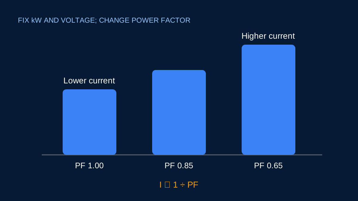
If active power and voltage stay fixed, reducing power factor makes the denominator smaller and current larger. Nothing mysterious has been added to the useful work. The supply is carrying more apparent power to deliver the same kW.
A 100 kW example at 415 V
| Power factor | Line current | Apparent power |
|---|---|---|
| 1.00 | 139.12 A | 100.00 kVA |
| 0.95 | 146.44 A | 105.26 kVA |
| 0.80 | 173.90 A | 125.00 kVA |
| 0.70 | 198.74 A | 142.86 kVA |
The table holds active power at 100 kW. At 0.70 power factor, the current is roughly 43% higher than at unity power factor.
Why the extra current matters
Conductor heating is related to current squared and resistance. Higher current can therefore increase distribution loss and voltage drop. It also uses capacity in transformers, cables and switchgear that must carry RMS current regardless of how much of the apparent power becomes active work.
This does not mean every low-power-factor reading demands a capacitor bank. Lightly loaded motors, changing production states and distorted waveforms can make one measurement unrepresentative.
Measure the operating profile
Power factor can change through a shift as machines cycle. Record active power, current, voltage and power factor together over a representative period. If loads are controlled by drives or electronic converters, examine waveform quality and the instrument’s measurement capability.
Correcting a number captured at one moment can create overcorrection when the load falls. Automatic staged systems exist because operating conditions are not always fixed.
Current reduction is not equipment selection
The calculator shows the idealised before-and-after current and the preliminary kVAr difference. A real design still needs to consider capacitor voltage rating, stage size, switching frequency, harmonics, detuning, ventilation, protection and the risk of leading power factor.
Use the relationship to understand why current changed and to estimate the scale of a problem. Then use measurements and a power-quality study to decide what action is appropriate.
Hold the right quantities constant
The statement “lower power factor means higher current” assumes active power and voltage stay constant. For balanced three phase:
I = P ÷ (√3 × VLL × PF)
At 50 kW and 415 V, PF 0.95 gives about 73.22 A. At PF 0.70, the same active power requires about 99.39 A. That is roughly 36% more current in the ideal comparison.
If current is held constant instead, lower power factor means less active power is delivered. Always state what is fixed before comparing two cases. Otherwise a mathematically correct sentence can be applied to the wrong operating question.
What the higher current affects
Current contributes to conductor and transformer loading. Resistive loss varies approximately with current squared, so an increase in current can increase losses more sharply than the percentage change in current itself. Voltage drop can also rise because the current and its phase relationship appear in the AC drop equation.
That does not mean a simple PF calculation proves a specific energy saving. Network resistance, load duration, harmonic content and where correction is connected all matter. Measurements before and after a change are needed for a defensible site claim.
Displacement PF and total PF
The familiar cosine relationship is displacement power factor for sinusoidal quantities. Nonlinear loads distort current, and total power factor can be lower even when the fundamental displacement angle looks good. A basic capacitor may improve displacement PF while leaving harmonic distortion unresolved—or can interact badly with it.
When drives, rectifiers, electronic lighting or switched-mode supplies are significant, obtain waveform and harmonic data. A single number from a display should be recorded with the instrument, measurement point and load state.
Correction near the load versus centrally
Correction connected close to a load can reduce reactive current in upstream conductors while that load runs. A central bank may be easier to control across many loads but does not remove reactive current from every downstream section. The preferred arrangement depends on operating patterns, switching and the distribution system.
ElectricalDyev calculates the ideal kVAr difference and before/after line current. It does not choose a location or switching strategy. Use its result to frame the measurement and design questions, then have the complete system reviewed before equipment selection.
Sources and limits
Preliminary engineering aid only. Power factor varies with load and waveform; correction equipment requires a separate harmonic and resonance assessment.
Verify applicable laws, standards, manufacturer data and project conditions with a qualified electrical professional before construction, procurement or regulatory submission.
CONTINUE READING
Related articles
Power and current
How much kVAr is needed to improve power factor?
The kVAr formula is straightforward. Choosing equipment safely still requires harmonic, resonance and switching studies.
Power and current
kW, kVA and kVAr: what each number tells you
These three quantities are related, but they answer different questions about an AC load and its effect on the supply.
Power and current
20 kW to amps at 415 V: a worked three-phase example
At 415 V three phase, 20 kW can mean several different line currents because operating power factor and efficiency matter.